Crushing and dust collection device for construction

A technology of dust removal device and construction, applied in grain processing and other directions, can solve the problems of flying fine particles, unstable rotation of grinding rollers, pollution, etc., to reduce harm, maintain stable rotation, and avoid environmental pollution.

Inactive Publication Date: 2018-09-04
重庆谦谦装饰工程有限公司
View PDF12 Cites 2 Cited by
  • Summary
  • Abstract
  • Description
  • Claims
  • Application Information

AI Technical Summary

Problems solved by technology

[0006] The purpose of the present invention is to provide a building crushing and dust removal device to solve the problem of unstable rotation of the crushing roller and pollution caused by flying fine particles

Method used


Image

  • Crushing and dust collection device for construction
  • Crushing and dust collection device for construction
  • Crushing and dust collection device for construction

Examples


Embodiment 1

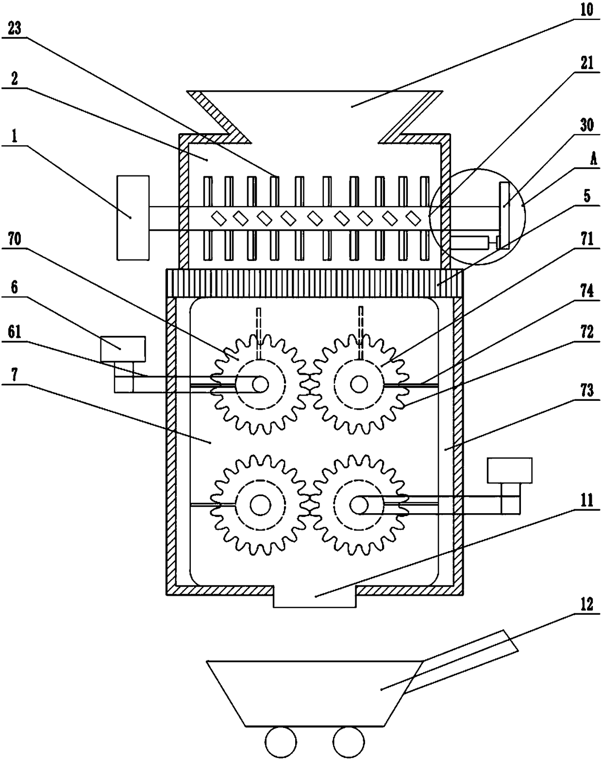
[0032] Such as figure 1 As shown, a building crushing dust removal device includes a first drive motor 1, a first crushing chamber 2, a second crushing chamber 7 and a filter screen 5 between the first crushing chamber 2 and the second crushing chamber 7, the first There is a feed port 10 above the crushing chamber 2, and a discharge port 11 is located at the bottom of the second crushing chamber 7. The first crushing chamber 2 is located above the second crushing chamber 7 and the two crushing chambers are connected.

[0033] Two transverse crushing rollers are arranged in the first crushing chamber 2, one is the active crushing roller 21, the other is the driven crushing roller 22, and several hammerheads 23 are arranged on the crushing rollers; Both ends extend out of the first crushing chamber 2, the left end of the active crushing roller 21 is connected with the first drive motor 1, the right end is connected with the first gear plate 30, and the right end of the driven c...

Embodiment 2

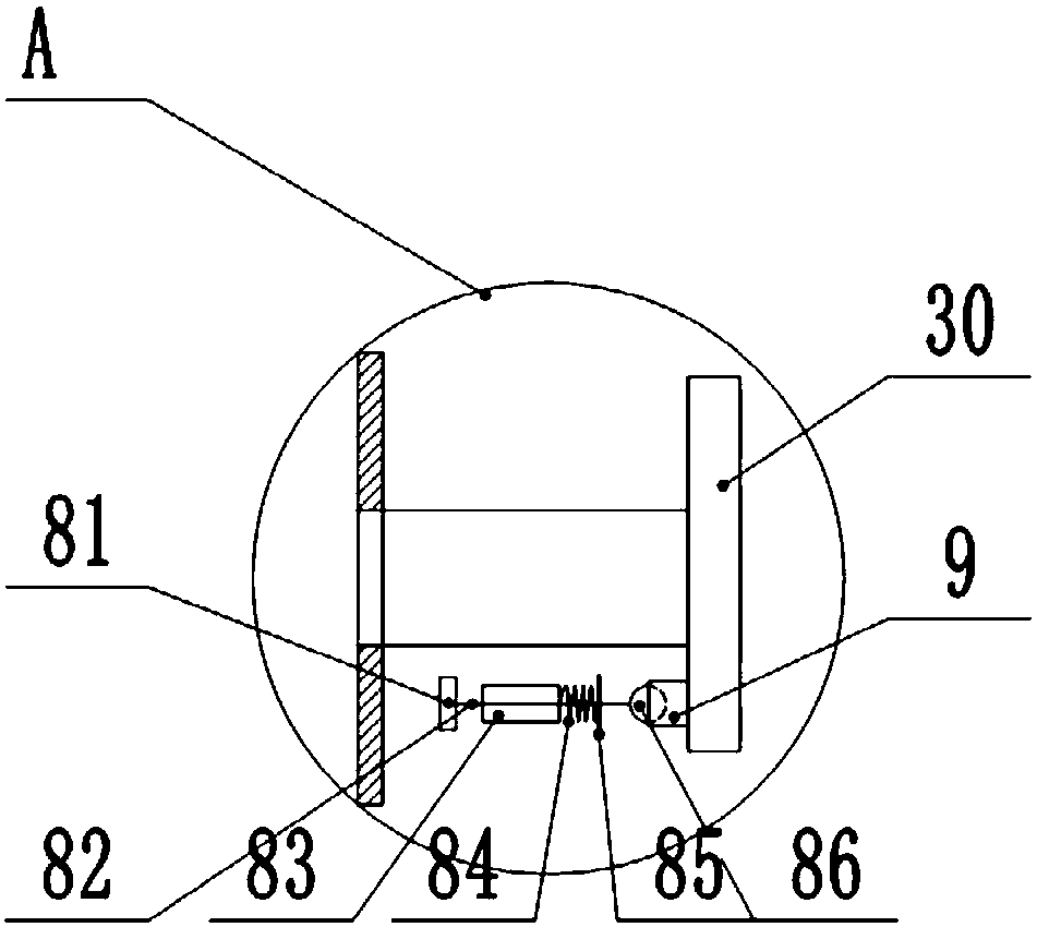
[0040] Such as image 3 As shown, the present embodiment is provided with a vibration mechanism on the basis of Embodiment 1, and its vibration mechanism is composed of a vibration plate 81, a connecting rod 82, a sleeve 83, a spring 84, a baffle plate 85 and a ball 86, and the sleeve 83 is installed On the bracket, the sleeve 83 is slidingly connected with the connecting rod 82, the left end of the connecting rod 82 is connected with the vibrating plate 81, and the right end is connected with the ball 86; the baffle plate 85 is arranged on the connecting rod 82 between the sleeve 83 and the ball 86, and the spring 84 is connected between the sleeve 83 and the baffle 85 . A wedge-shaped protrusion 9 is provided on the gear plate, and the wedge surface of the wedge-shaped protrusion 9 is distributed along the tangential direction of the gear plate, allowing the ball 86 to roll along its wedge surface, wherein the vibration mechanism is located between the first crushing chamber...

Embodiment 3

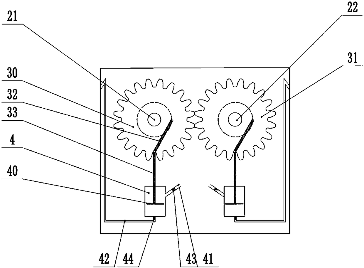
[0043] Such as figure 1 and Figure 4 As shown, the difference between this embodiment and Embodiment 1 and Embodiment 2 is that the pair of rollers in the second crushing chamber 7 is divided into a driving roller 70 and a driven roller 71, and the rollers are formed along the vertical plane where the centerline of the pair of rollers is located. There are multiple groups, and the positions of the multiple pairs of rollers are staggered, and the synchronous belt 61 is connected on the driving roller 70 . An electrostatic adsorption plate 73 is installed on the inner wall of the second crushing chamber 7, plates 74 are arranged on the end faces of the driving roller 70 and the driven roller 71, and the two scrapers 74 are symmetrical, and the two scrapers 74 sweep along with the rotation of the counter rollers. Electrostatic adsorption plate 73 surface.

[0044] Owing to gas blowing in the first crushing chamber 2, the gas will inevitably pass through the filter screen 5 and...


PUM


Abstract

The invention belongs to the technical field of construction equipment, and particularly discloses a crushing and dust collection device for construction. The crushing and dust collection device for construction comprises a first crushing cavity, a second crushing cavity and a filter screen located between the first crushing cavity and the second crushing cavity. Transverse crushing rollers are arranged in the first crushing cavity. One end of one crushing roller is connected with a first driving motor, and the other end of the crushing roller is connected with a slider-crank mechanism. A support is arranged on the outer wall of the first crushing cavity. A cylinder is mounted on the support. An air pipe provided with an air inlet one-way valve is arranged on the lateral portion of the cylinder. An air outlet pipe stretching into the first crushing cavity and provided with an air outlet one-way valve is arranged at the bottom of the cylinder. The crank-slider mechanism is used for pushing air in the cylinder to enter the first crushing cavity. A pair of rollers is arranged in the second crushing cavity and driven by a second motor through a synchronous belt. According to the crushing and dust collection device, the crushing rollers can rotate stably, and pollution caused by flying fine particles is avoided; and meanwhile, the fine particles can be transported in containers, sothat the cost is reduced, and the work efficiency is improved.

Description

technical field [0001] The invention belongs to the technical field of construction equipment, and specifically discloses a construction crushing and dust removal device. Background technique [0002] With the acceleration of urbanization and the rapid development of the construction industry, there will be more and more construction waste, such as old city reconstruction, urban village demolition, road reconstruction, etc., among which the amount of concrete and masonry construction waste is the largest. The treatment method is to bury it, be transported by the construction unit to the outskirts for open-air stacking, or be pulverized by a pulverizer. [0003] In the process of using the pulverizer, the pulverized fine particles fly around with the rotation of the pulverizing device, causing serious pollution and endangering the health of the staff. [0004] Chinese patent CN104307619 A discloses a crushing device dedicated to construction, including a first motor, a secon...

Claims


Application Information

Patent Timeline
IPC IPC(8): B02C13/02B02C13/20B02C4/08B02C23/16B02C23/38
CPCB02C13/02B02C4/08B02C13/20B02C23/16B02C23/38B02C2023/165B02C2201/06
Inventor 张谦
Owner 重庆谦谦装饰工程有限公司
Why Eureka
Try Eureka