
Coal ash layered smashing device for chemical experiment

A crushing device and chemical experiment technology, applied in the field of grinding and processing machinery, to achieve the effect of simple operation

Pending Publication Date: 2018-09-04
HUANGHE S & T COLLEGE
View PDF0 Cites 0 Cited by
  • Summary
  • Abstract
  • Description
  • Claims
  • Application Information

AI Technical Summary

Problems solved by technology

[0003] Aiming at the common defects and problems of existing grinding equipment, the present invention provides a fly ash layered pulverization device for chemical experiments to achieve the purpose of improving grinding precision and grinding efficiency

Method used


Image

  • Coal ash layered smashing device for chemical experiment
  • Coal ash layered smashing device for chemical experiment
  • Coal ash layered smashing device for chemical experiment

Examples


Embodiment 1

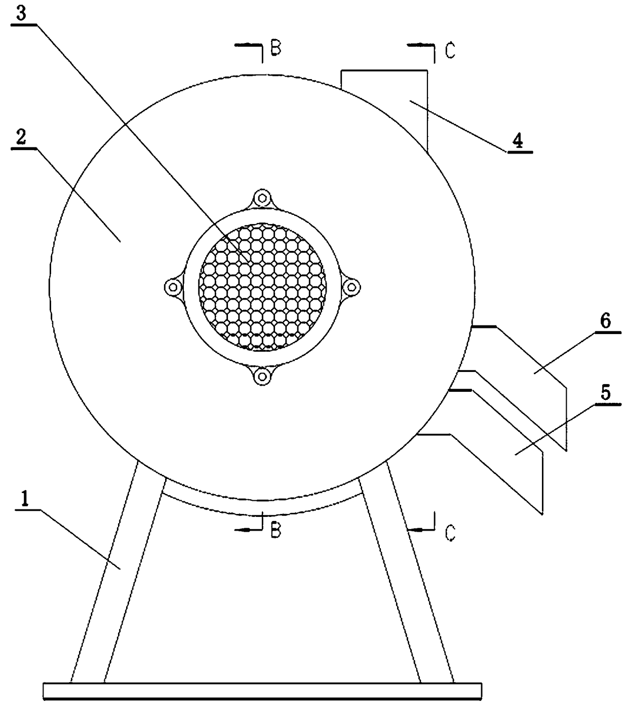
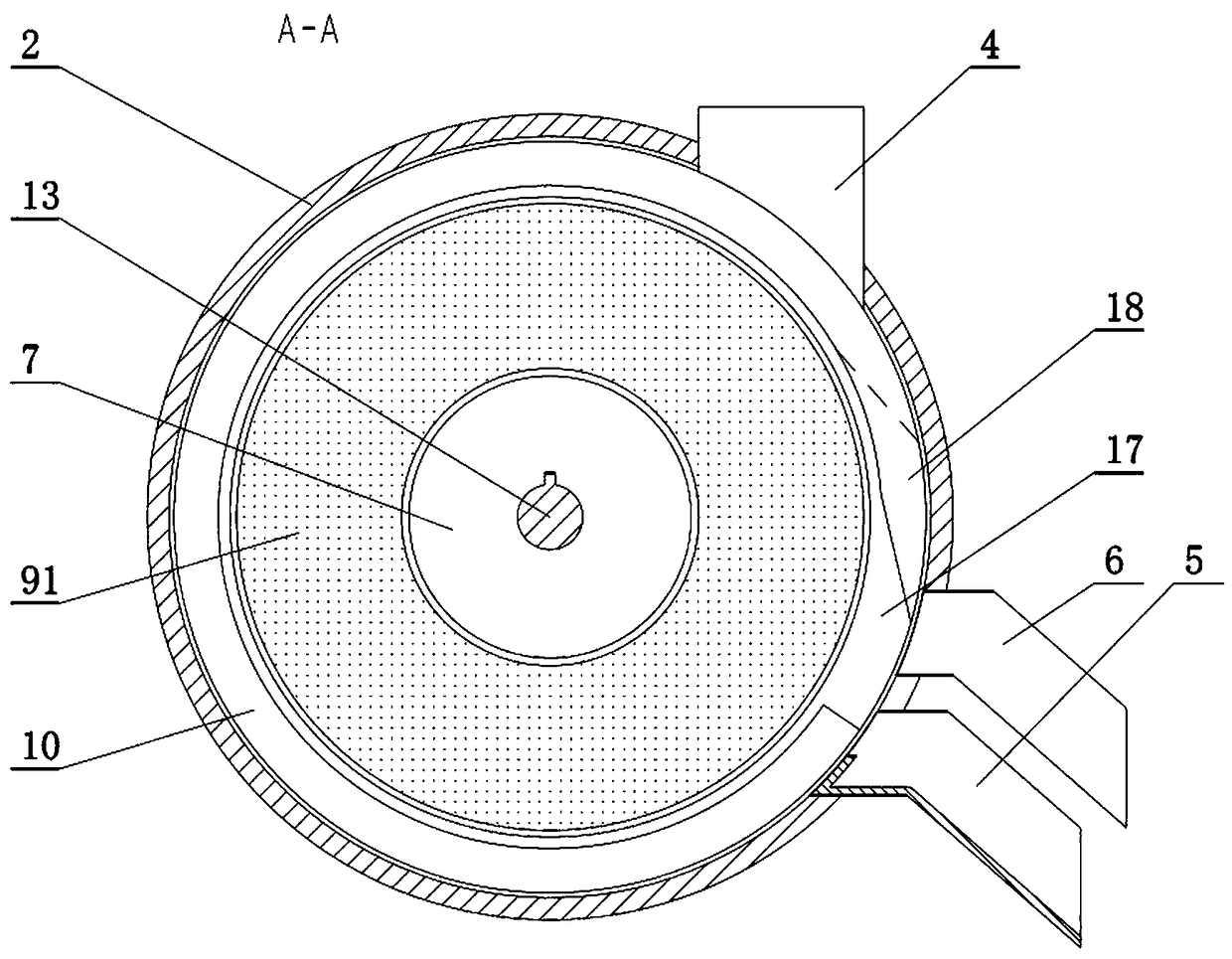
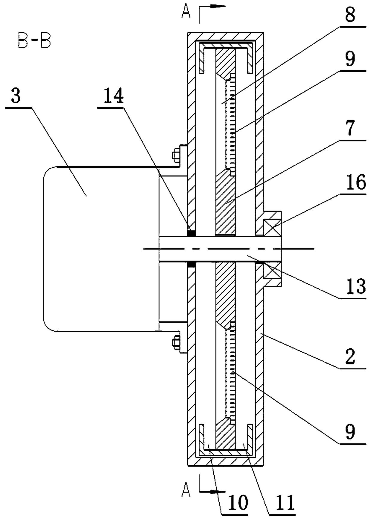
[0021] Embodiment 1: A kind of fly ash layered crushing device for chemical experiments, see figure 1 and Figure 4 As shown, it includes a sealing body 2 fixed on the bracket 1, and the sealing body 2 includes a sealing door fixed on the main body part and the side of the bracket 1. The motor 3 is installed on one side of the sealing body 2 , and the rotating shaft of the motor extends into the inside of the sealing body 2 and the turntable main body 7 is installed. At the same time, a feed hopper 4 is arranged on one side of the sealing body 2 .

[0022] see image 3 As shown, the turntable main body 7 includes an annular transparent area, which divides the turntable main body 7 into an inner disc body and an outer ring body, and the two are connected as a whole through the radial connecting rod of the annular area.

[0023] An annular rubbing filter screen 9 is matched and fixed in the annular transparent area, see Figure 5 As shown, the front side of the annular rubbi...

Embodiment 2

[0026] Embodiment 2: on the basis of embodiment 1, see Figure 4 As shown, on the inner wall of the sealing body 2 near the back side of the ring-shaped grinding filter screen 9, a rolling roller 19 is installed through the axle seat, and at the same time, on the sealing body near the front side of the ring-shaped grinding filter screen 9 2. Support rollers 20 are installed on the inner wall, and the support rollers 20 and rolling rollers 19 are respectively tangent to the two sides of the annular rubbing filter screen 9 on the same straight line. Utilize rolling roller 19 to carry out rolling on the back side of annular rubbing filter screen 9, make the powder passing through the screen continue to be rolled. The lamination roller 19 is supported by the support roller 20 , thereby increasing the lamination strength of the lamination roller 19 . In the present invention, since the ring-shaped grinding filter screen 9 is rotating, the linear speeds of its inner edge and outer ...

Embodiment 3

[0027] Embodiment 3: On the basis of Embodiment 2, on the inner wall of the sealing body 2 near the back side of the annular grinding filter screen 9, a brush layer parallel to the axial direction is fixed, and the end face of the brush layer is Plane and parallel with the ring-shaped grinding filter screen 9 back sides.


PUM


Abstract

The invention discloses a coal ash layered smashing device for a chemical experiment. The coal ash layered smashing device for the chemical experiment comprises a support, a motor and a smashing mechanism; an annular pass-through area is arranged on a rotary plate body; an annular rubbing and grinding filter screen mesh is fixed to the annular pass-through area in a matching way; a hopper matchingnozzle is arranged at a part, located on the inner side of a sealing body, of a feeding hopper. The coal ash layered smashing device for the chemical experiment provided by the invention can be usedfor rubbing and grinding solid mixtures or wastes into powder, and during a rubbing, grinding and smashing process, the annular rubbing and grinding filter screen is used for directly filtering and separating powder with fine granularity, so that components can be further favorably used for experiments.

Description

Technical field: [0001] The invention belongs to the technical field of grinding processing machinery, and in particular relates to a fly ash layered crushing device for chemical experiments. Background technique: [0002] Grinding is an important processing method in ultra-precision machining. Its advantages are high processing accuracy and a wide range of processing materials. However, traditional grinding has disadvantages such as low processing efficiency, high processing cost, unstable processing accuracy and processing quality. The grinding machine commonly used in the chemical production process is directly provided with a funnel at the entrance of the grinding machine, causing the objects to be ground to scatter out, and suitable rapid grinding cannot be performed. In addition, the existing equipment for material grinding is suitable for large-scale crushing and processing, but not suitable for small-scale precision crushing in laboratories. Due to the limited numb...

Claims


Application Information

Patent Timeline
IPC IPC(8): B02C15/14B02C23/16
CPCB02C15/14B02C23/16B02C2023/165
Inventor 侯巧芝吴建丽付丽娜信建豪庞蓉
Owner HUANGHE S & T COLLEGE
Learn More