
Welding device used for underground engineering waste water pipeline and working method of welding device

A welding device and underground engineering technology, applied in auxiliary devices, welding equipment, auxiliary welding equipment, etc., can solve the problems of slow delivery time, uneven welding seam, and inability to guarantee welding quality.

Inactive Publication Date: 2018-09-04
XUZHOU UNIV OF TECH
View PDF5 Cites 0 Cited by
  • Summary
  • Abstract
  • Description
  • Claims
  • Application Information

AI Technical Summary

Problems solved by technology

Due to human factors, the welding speed is not stable, resulting in uneven weld seam, low welding efficiency, which affects the welding quality; and working under high temperature conditions and dusty conditions will cause great harm to the human body
[0003] In addition, the traditional manual welding method has problems such as low welding efficiency, high labor intensity, and unstable welding quality. It has been gradually replaced by automatic welding equipment. The three-claw plate and pneumatic cylinder are used to fix the welded parts, which will cause many problems such as slow delivery time and inability to guarantee welding quality.

Method used


Image

  • Welding device used for underground engineering waste water pipeline and working method of welding device
  • Welding device used for underground engineering waste water pipeline and working method of welding device
  • Welding device used for underground engineering waste water pipeline and working method of welding device

Examples


Embodiment 1

[0071] According to the following steps, the baffle plate 8-6-2-2-2 of the present invention is manufactured, and in parts by weight:

[0072] Step 1: Add 2757 parts of ultrapure water with a conductivity of 5.53μS / cm into the reactor, start the stirrer in the reactor at a speed of 78rpm, start the heating pump, and raise the temperature in the reactor to 79°C; add in order 21 parts of 5-[[(1,1-dimethylethoxy)carbonyl]amino]-1,3-piperidinedicarboxylic acid 3-methyl 1-(phenylmethyl)ester, 1-(p 131 parts of tosyl)-indole-2-boronic acid, 69 parts of tert-butyl 5-nitro-2-(pyridin-4-yl)benzylmethylcarbamate, stir until completely dissolved, and adjust the pH value to 6.0 , adjust the speed of the agitator to 143rpm, the temperature is 117°C, and the chemical reaction is 23 hours;

[0073]Step 2: Take 142 parts of tert-butyl 1-(4-(isoindoline-2-carboxamide)phenyl)pyrrolidin-3-ylcarbamate, 1,2,3,4-tetrahydro-3 80 parts of -(2-methyl-5-(thiocarbamoylmethoxy) phenyl)-2-oxoquinazoline...

Embodiment 2

[0078] The hollow groove plate 8-6-2-2-2 of the present invention is manufactured according to the following steps, and is counted in parts by weight:

[0079] Step 1: Add 3207 parts of ultrapure water with a conductivity of 6.98μS / cm into the reactor, start the stirrer in the reactor at a speed of 105rpm, start the heating pump, and raise the temperature in the reactor to 105°C; add in sequence 5-[[(1,1-dimethylethoxy)carbonyl]amino]-1,3-piperidinedicarboxylic acid 3-methyl 1-(phenylmethyl)ester 56 parts, 1-(p 166 parts of tosyl)-indole-2-boronic acid, 109 parts of tert-butyl 5-nitro-2-(pyridin-4-yl)benzylmethylcarbamate, stir until completely dissolved, and adjust the pH value to 7.0 , adjust the speed of the agitator to 189rpm, the temperature is 143°C, and the chemical reaction is 30 hours;

[0080] Step 2: Take 161 parts of tert-butyl 1-(4-(isoindoline-2-carboxamide)phenyl)pyrrolidin-3-ylcarbamate, 1,2,3,4-tetrahydro-3 129 parts of -(2-methyl-5-(thiocarbamoylmethoxy) ph...

Embodiment 3

[0085] The hollow groove plate 8-6-2-2-2 of the present invention is manufactured according to the following steps, and is counted in parts by weight:

[0086] Step 1: Add 3656 parts of ultrapure water with a conductivity of 8.43μS / cm into the reactor, start the stirrer in the reactor at a speed of 133rpm, start the heating pump, and raise the temperature in the reactor to 131°C; add in sequence 91 parts of 5-[[(1,1-dimethylethoxy)carbonyl]amino]-1,3-piperidinedicarboxylic acid 3-methyl 1-(phenylmethyl)ester, 1-(p 208 parts of tosyl)-indole-2-boronic acid, 149 parts of tert-butyl 5-nitro-2-(pyridin-4-yl)benzylmethylcarbamate, stir until completely dissolved, and adjust the pH value to 7.9 , adjust the speed of the agitator to 235rpm, the temperature is 171°C, and the chemical reaction is 35 hours;

[0087] Step 2: Take 182 parts of tert-butyl 1-(4-(isoindoline-2-carboxamide)phenyl)pyrrolidin-3-ylcarbamate, 1,2,3,4-tetrahydro-3 178 parts of -(2-methyl-5-(thiocarbamoylmethoxy)...


PUM

PropertyMeasurementUnit
Conductivityaaaaaaaaaa
Particle sizeaaaaaaaaaa

Abstract

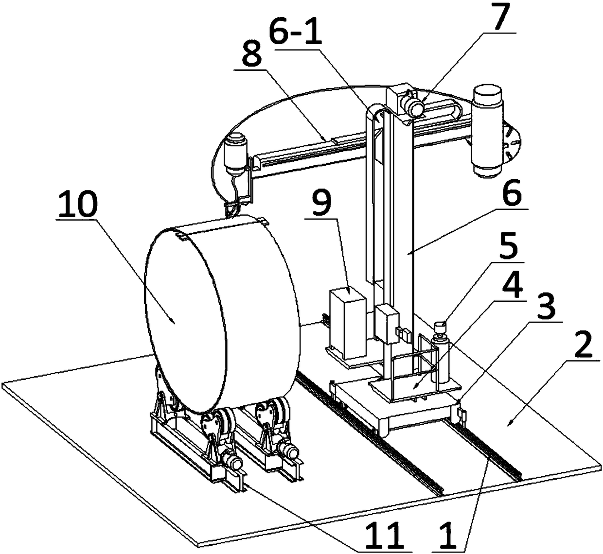
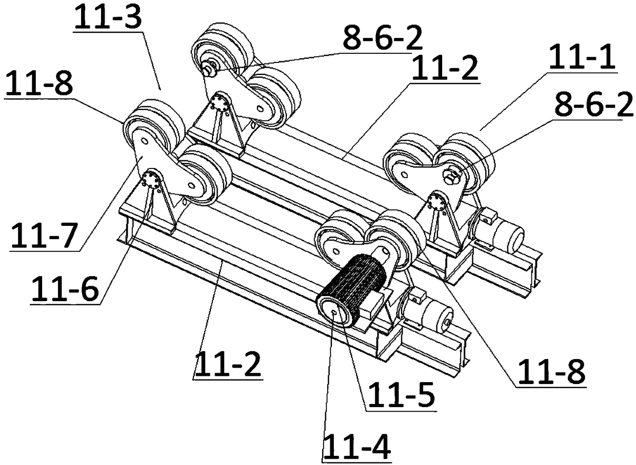
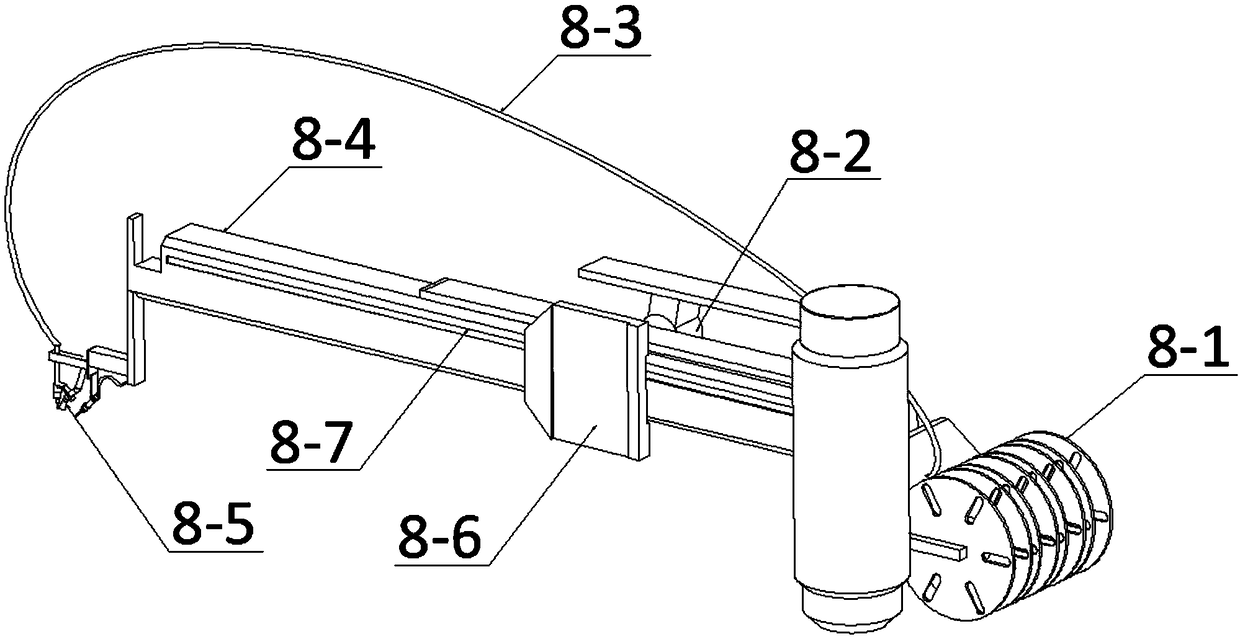
The invention discloses a welding device used for underground engineering waste water pipelines and a working method of the welding device. The left side of the upper part of a fixed plate is fixedlyconnected with a workpiece holder; a rotating platform is rotatably connected with the upper part of a moving trolley through a rotating shaft fixedly connected with the lower part of the rotating platform; a support pillar is fixedly arranged at the front side of the upper part of the rotating platform; the front side of the support pillar is provided with a vertical slideway; the top part of thesupport pillar is fixedly provided with a vertical driving motor; a welding arm consists of a fixed arm and a sliding arm; the lower part of the left end of the sliding arm is fixedly connected withwelding tongs; the right end of the fixed arm is fixedly connected with reels; one side, near the slideway, of a slider is provided with two sliding chutes II which extend vertically and of which thecross sections are in a shape of T; a sliding rail of which the cross section is in the shape of T is glidingly assembled in each of the two sliding chutes II; upper ends and lower ends of the two sliding rails are respectively and fixedly connected with the upper end and the lower end of the slideway; and two lubricating oil filling devices are fixedly arranged at the front side of the slider ina manner of being respectively corresponding to the sliding chutes II. The welding device is convenient and fast in operating process and high in operation efficiency, and is suitable for welding operation of round workpieces.

Description

technical field [0001] The invention belongs to the technical field of welding equipment, and in particular relates to a welding device for underground engineering waste water pipelines and a working method thereof. Background technique [0002] In the process of traditional manual welding of pipes, since the outer contour of the pipe is a circumferential surface, the weld seam on its surface is also an arc-shaped surface. During manual welding, either the oxygen cylinder does not move, and the outer contour of the pipe is welded manually. ; Either the pipeline does not move, and the oxygen cylinder is welded around the pipeline to its outer contour. Due to human factors, the welding speed is not stable, resulting in uneven weld seam, low welding efficiency, which affects the welding quality; and working under high temperature and dusty conditions will cause great harm to the human body. [0003] In addition, the traditional manual welding method has problems such as low we...

Claims


Application Information

Patent Timeline
IPC IPC(8): B23K37/02B23K37/053
CPCB23K37/02B23K37/053B23K37/0533
Inventor 梁峙梁骁马捷韩宝平刘喜坤许旭张明胜陈兴祥董平
Owner XUZHOU UNIV OF TECH
Learn More