Positioning device for electronic component

A technology for electronic components and positioning devices, applied in auxiliary devices, other manufacturing equipment/tools, auxiliary welding equipment, etc., can solve the problems of complex procedures, high labor intensity, low efficiency, etc., to reduce labor intensity, improve production efficiency, The effect of continuous welding

Active Publication Date: 2018-09-04
山东贝斯特信息科技有限公司
View PDF7 Cites 1 Cited by
  • Summary
  • Abstract
  • Description
  • Claims
  • Application Information

AI Technical Summary

Problems solved by technology

[0003] For some large-scale electronic component manufacturers, there is a great demand for electronic components. On the one hand, manual welding requires higher welding skills for welders, and the quality of products handled by different welders cannot be consistent; on the other hand, the entire The process requires manual positioning of the electronic components, then welding, and then releasing the positioning of the electronic components and removing the electronic components. The procedure is complicated, the labor intensity is high, and the efficiency is low, which cannot meet the market vacancies with increasing demand.

Method used


Image

  • Positioning device for electronic component
  • Positioning device for electronic component
  • Positioning device for electronic component

Examples


Embodiment Construction

[0017] Further detailed explanation through specific implementation mode below:

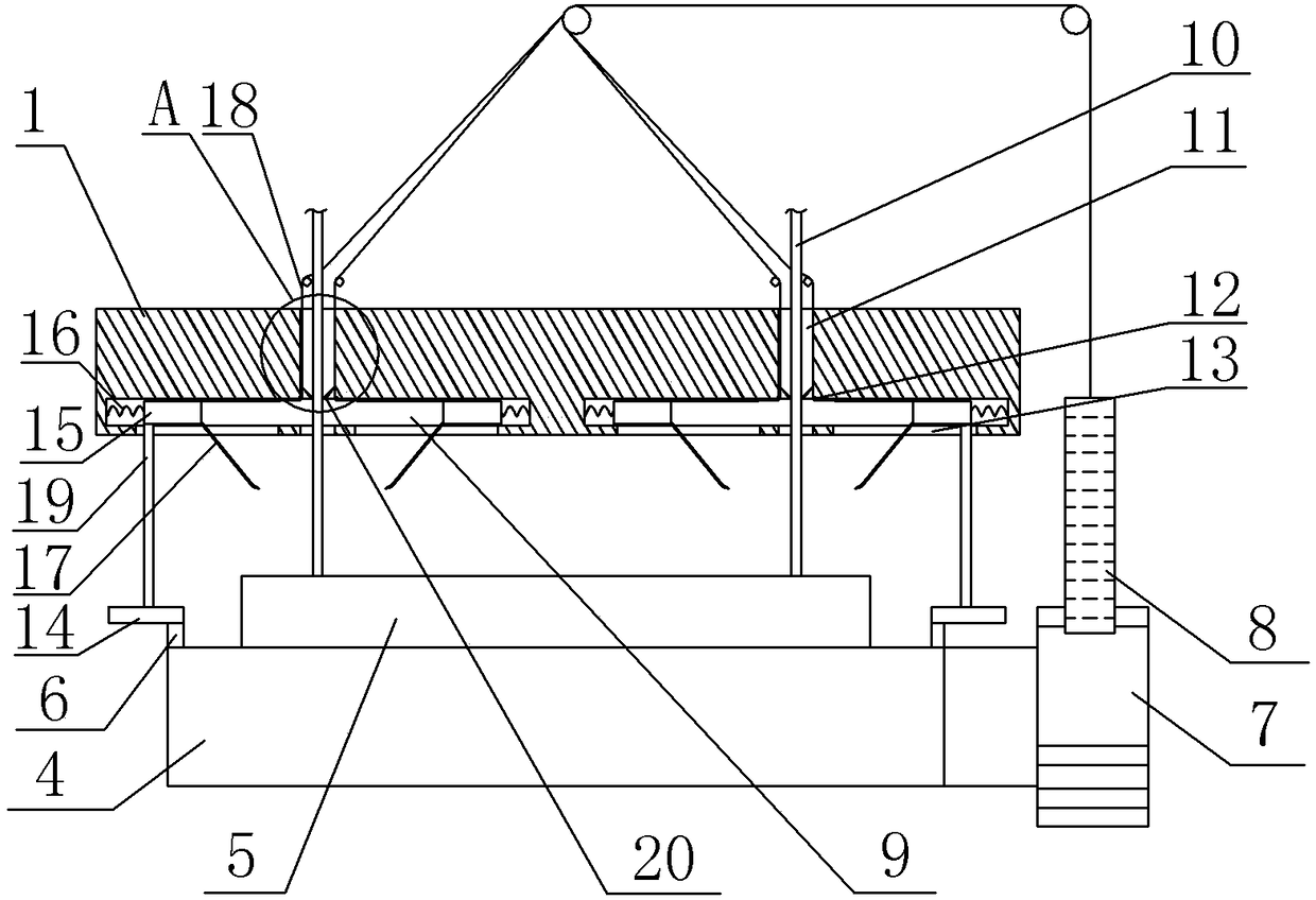
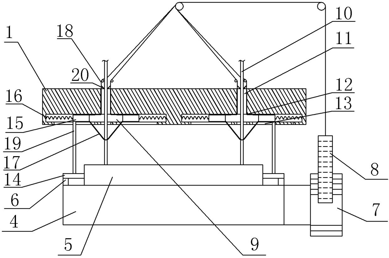
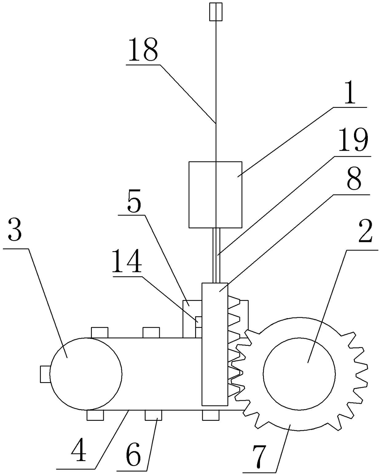
[0018] The reference signs in the drawings of the description include: beam 1, driving roller 2, driven roller 3, conveyor belt 4, electronic component 5, limit block 6, incomplete gear 7, rack 8, slideway 9, pin 10 , Through hole 11, roller 12, square hole 13, positioning block 14, slide block 15, extension spring 16, cutter 17, stay cord 18, connecting rod 19, scraper 20.

[0019] Such as figure 1 , 2 The shown positioning device for electronic components includes a conveying mechanism, a beam 1 and two positioning and cutting mechanisms. Such as image 3 As shown, the transmission mechanism includes a servo motor, a driving roller 2, a driven roller 3 and a conveyor belt 4, the servo motor is fixed on the frame, and the driving roller 2 and the driven roller 3 are rotatably arranged on the frame, wherein the driving roller 2 and the servo The output shaft of the motor is fixedly connected ...


PUM


Abstract

The invention relates to the field of production of electronic components, in particular to a positioning device for an electronic component. The positioning device comprises a machine frame, a conveying mechanism, a cross beam and two positioning cutting mechanisms, wherein the conveying mechanism comprises a driving roller, a driven roller and a conveying belt; an intermittent gear is coaxiallyconnected on the driving roller, and a rack meshed with the intermittent gear is arranged on the machine frame in a mode of vertically sliding; a horizontal slideway is arranged in the cross beam, anda through hole for enabling a pin to pass through is vertically formed in the cross beam; each positioning cutting mechanism comprises a positioning block and two cutting units, and each cutting unitcomprises a sliding block, a tension spring, a cutting knife and a stay cord, the sliding block is arranged in the slideway in a sliding mode, one end of the tension spring is fixedly connected withthe cross beam, the free end of the tension spring is fixedly connected with the sliding block, the cutting knife is obliquely arranged on the sliding block, the positioning block is fixedly connectedwith the sliding block, one end of the stay cord is fixedly connected with the sliding block, the other end of the stay cord is fixedly connected with the rack, and a scraper is arranged on the staycord. According to the technical scheme, the positioning device can automatically position the electronic component and continuously weld the electronic component.

Description

technical field [0001] The invention relates to the field of electronic component production, in particular to a positioning device for electronic components. Background technique [0002] At present, with the rapid development of electronic technology, the use of electronic components is becoming more and more extensive. Usually, after the electronic component core is manufactured, it is necessary to lead out the pins from the electronic component. The common way is to fix and weld two pins on the electronic component core. At present, the commonly used pin material is copper wire. Before welding, the electronic components need to be positioned and fixed, and then one end of the pin is contacted with the corresponding position of the electronic components, and then manual welding is performed respectively. [0003] For some large-scale electronic component manufacturers, there is a great demand for electronic components. On the one hand, manual welding requires higher weld...

Claims


Application Information

Patent Timeline
IPC IPC(8): B23K37/04B23K37/00B23P23/04B23P23/06B23K101/36
CPCB23K37/00B23K37/04B23P23/04B23P23/06
Inventor 刘光全
Owner 山东贝斯特信息科技有限公司
Why Eureka
Try Eureka