Hardware die machining cutting machine convenient to move

A mold processing and cutting machine technology, applied in metal processing machinery parts, metal processing equipment, manufacturing tools, etc., can solve the problem of not being easy to move, and achieve the effect of improving the use value, increasing the use effect, and improving the stability.

Inactive Publication Date: 2018-09-04
李明科
View PDF0 Cites 1 Cited by
  • Summary
  • Abstract
  • Description
  • Claims
  • Application Information

AI Technical Summary

Problems solved by technology

[0005] Aiming at the deficiencies of the prior art, the present invention provides a cutting machine for metal mold processing that is easy to move, which solves the problem of not having the ability to move easily

Method used


Image

  • Hardware die machining cutting machine convenient to move
  • Hardware die machining cutting machine convenient to move

Examples


Embodiment Construction

[0020] The following will clearly and completely describe the technical solutions in the embodiments of the present invention with reference to the accompanying drawings in the embodiments of the present invention. Obviously, the described embodiments are only some, not all, embodiments of the present invention. Based on the embodiments of the present invention, all other embodiments obtained by persons of ordinary skill in the art without making creative efforts belong to the protection scope of the present invention.

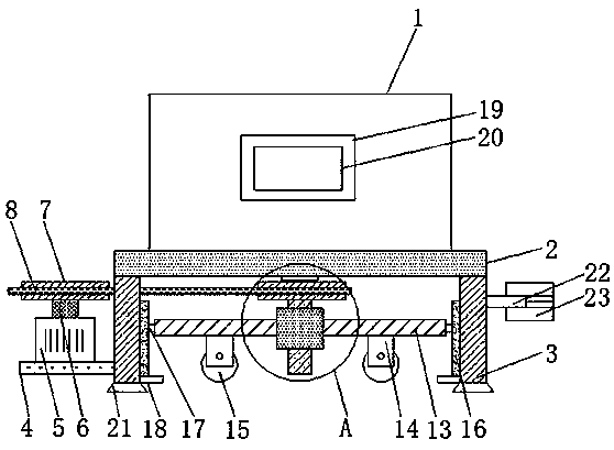
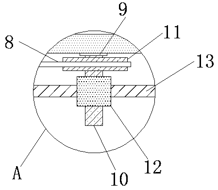
[0021] see Figure 1-2 , the present invention provides a technical solution: a cutting machine for metal mold processing that is easy to move, including a cutting machine body 1, a base 2 is fixedly connected to the bottom of the cutting machine body 1, and two phases are fixedly connected to the bottom of the base 2 Symmetrical support columns 3, the opposite sides of the two support columns 3 are fixedly connected with a slide rail 16, and the inside of the...


PUM


Abstract

The invention discloses a hardware die machining cutting machine convenient to move. The hardware die machining cutting machine comprises a cutting machine body, and the bottom of the cutting machinebody is fixedly connected with a base. The bottom of the base is fixedly connected with two symmetric supporting columns. A containing plate is fixedly connected to one side face of one supporting column. The upper surface of the containing plate is fixedly connected with a forward and reverse rotation motor. The output end of the forward and reverse rotation motor is fixedly connected with a rotation rod. The end, away from the forward and reverse rotation motor, of the rotation rod is fixedly connected with a first gear. The outer surface of the first gear is sleeved with a rack. The bottomof the base is fixedly connected with a bearing, the end, away from the base, of the bearing is provided with a threaded rod, and one end of the threaded rod is fixedly connected with an inner ring ofthe bearing. According to the hardware die machining cutting machine convenient to move, through structure cooperation, movement of the hardware die machining cutting machine can be achieved, the usage value of the hardware die machining cutting machine is improved, and wide popularization is facilitated.

Description

technical field [0001] The invention relates to the technical field of hardware mold processing equipment, in particular to a cutting machine for metal mold processing that is easy to move. Background technique [0002] Metal molds are used in industrial production to use various presses and special tools installed on the presses to make metal materials into parts or products of the required shape through pressure. These special tools are collectively referred to as rough machining of metal molds. The main goal is to pursue the material removal rate per unit time and prepare the geometric profile of the workpiece for semi-finishing. During the cutting process, the metal area of ​​the cutting layer changes, resulting in a change in the load on the tool, which makes the cutting process unstable. The wear rate is uneven and the quality of the machined surface is reduced. [0003] At present, cutting machines are needed for further processing in the processing of metal molds, a...

Claims


Application Information

Patent Timeline
Patent Type & Authority Applications(China)
IPC IPC(8): B23Q1/01B23Q1/25B23Q1/72B23Q1/00
CPCB23Q1/01B23Q1/00B23Q1/017B23Q1/25B23Q1/72
Inventor 李明科
Owner 李明科
Why Eureka
Try Eureka