
Industrial conveying robot

A handling robot, industrial technology, applied in the direction of manipulators, manufacturing tools, chucks, etc., can solve the problem that industrial robots cannot adapt to various object clamping, and achieve the effect of increasing stability and increasing clamping force.

Active Publication Date: 2018-09-04
宁波隆锐机械制造有限公司
View PDF6 Cites 13 Cited by
  • Summary
  • Abstract
  • Description
  • Claims
  • Application Information

AI Technical Summary

Problems solved by technology

[0004] In view of the above problems, the present invention provides an industrial handling robot, which has solved the problem that existing industrial robots cannot adapt to the clamping of various objects

Method used


Image

  • Industrial conveying robot
  • Industrial conveying robot
  • Industrial conveying robot

Examples


Embodiment 1

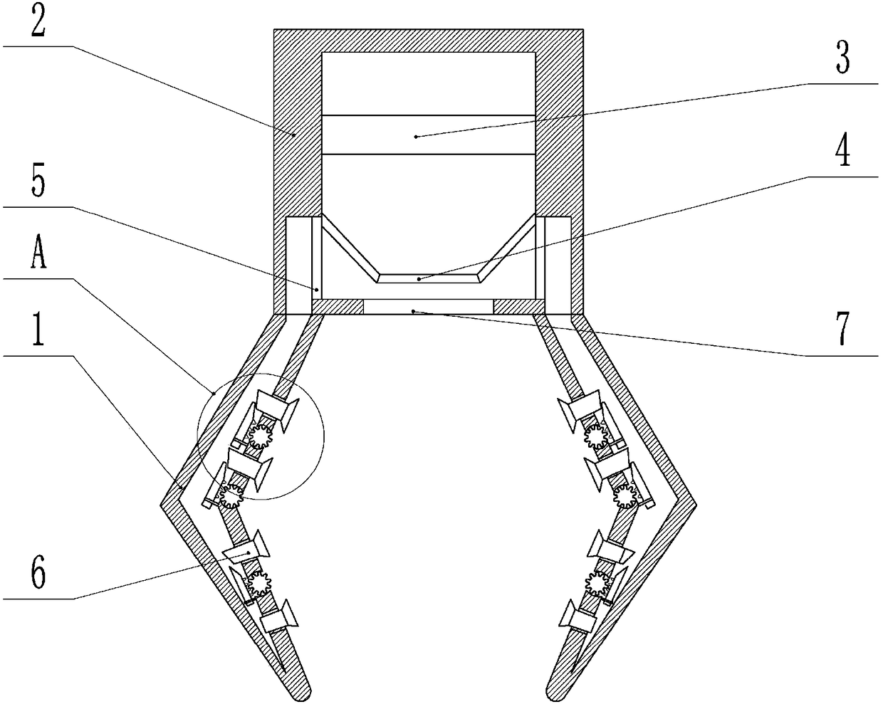
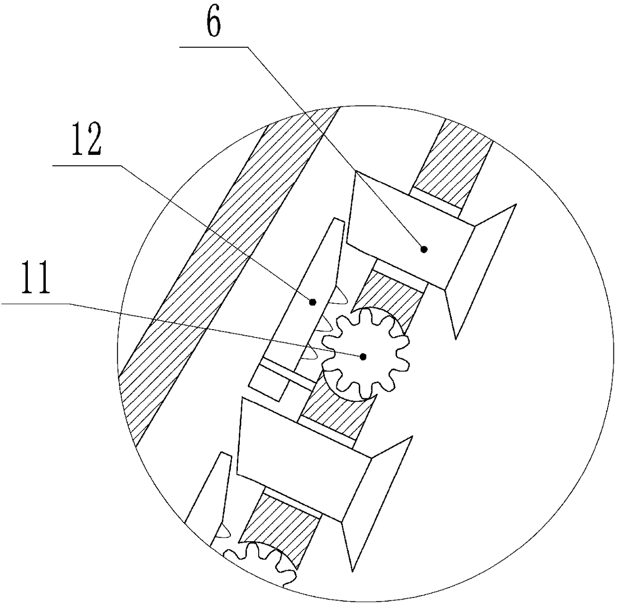
[0025] The embodiment is basically as attached figure 1 And attached figure 2Shown: the industrial handling robot, including the cylinder 2, the top of the cylinder 2 is provided with an inflator for inflating the cylinder 2, and the inflator can be an air pump; A microcontroller is electrically connected, and the microcontroller is electrically connected to the inflatable device. An air passage is provided on the left and right side walls of the lower end of the cylinder 2, and an opening 5 for communicating between the air passage and the chamber of the cylinder 2 is provided. 5 places are provided with a second solenoid valve; two clamping blocks 1 are detachably connected to the bottom of the cylinder 2 for clamping and transporting the workpiece. Extrusion channel, the side wall of the clamping block 1 close to the workpiece is provided with four slides, and the fastening block 6 is slidably connected in the slides, the clamping channel of the clamping block 1 and the v...

Embodiment 2

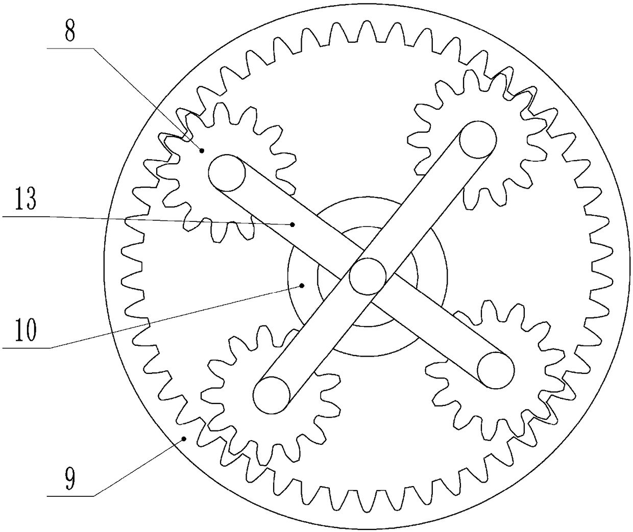
[0032] as attached image 3 As shown, the difference between the second embodiment and the first embodiment is that the industrial handling robot also includes a frame, and the frame is provided with an adjustment disc, and the adjustment disc includes an inner gear ring sleeve 9 which is rotatably connected to the frame, and the inner gear ring sleeve 9 There are four planetary pinions 8 evenly meshed inside, and the clamping block 1 is respectively arranged on the lower surface of the four planetary pinions 8 and hinged with the planetary pinions 8, and the two spaced apart planetary pinions 8 are rotatably connected with each other. Connecting rod 13, the intersection of two connecting rods 13 is provided with the rotating shaft that is rotatably connected with the frame, and the rotating shaft is provided with an annular elastic air bag 10 with the rotating shaft as the center of a circle, and the annular air bag 10 intersects with the connecting rod 13 and is connected by ...


PUM


Abstract

The invention relates to the field of industrial robots, in particular to an industrial conveying robot. The industrial conveying robot comprises a rack, wherein the rack is rotatably connected with inner gear rings and rotating shafts fixedly arranged in the central parts of the inner gear rings; the inner parts of the inner gear rings are symmetrically meshed with two groups of planetary pinionsby using the rotating shafts as a center; each group of two planetary pinions are arranged; a corresponding connecting rod is rotatably connected between the each group of planetary pinions; the middle position of the corresponding connecting rod is fixedly connected with the corresponding rotating shaft; clamping blocks for clamping objects are arranged on the each group of planetary pinions; extrusion channels are arranged in the clamping blocks; a side wall of the corresponding extrusion channel is connected with fastening blocks for fastening the objects in a sliding manner; the extrusionchannels positioned aside the fastening blocks are connected with anti-skid gears in a rotating manner; the anti-skid gears are connected with sealing sleeves which are placed in the extrusion channels and enables the gas to release out in a sleeving manner, and inclined surfaces are arranged on the fastening blocks positioned in anti-skid channels; the inner parts of the extrusion channels are connected with racks meshed with the anti-skid gears; and inclined surfaces matched with the inclined surfaces of the fastening blocks are arranged on the racks.

Description

technical field [0001] The invention relates to the field of industrial robots, in particular to an industrial handling robot. Background technique [0002] An industrial robot is a multi-joint manipulator or a multi-degree-of-freedom machine device for the industrial field. It can perform work automatically. It can accept human commands or run according to pre-programmed programs. Industrial robots can replace people in industrial production. Some monotonous, frequent and repetitive long-term operations, or operations in dangerous and harsh environments, such as stamping, die casting, heat treatment, welding, painting, plastic product forming, machining and simple assembly, etc. In the atomic energy industry and other departments, the handling or process operation of materials harmful to the human body is completed. In developed countries, the complete set of industrial robot automation production line equipment has become the mainstream of automation equipment and the futu...

Claims


Application Information

Patent Timeline
Patent Type & Authority Applications(China)
IPC IPC(8): B25J15/08B25J15/06
CPCB25J15/0616B25J15/08
Inventor 叶敏
Owner 宁波隆锐机械制造有限公司
Learn More