Three-state mechanical foot structure

A technology of mechanical feet and hinges, applied in the field of robot structure research, can solve problems such as a single environment

Pending Publication Date: 2018-09-04
FOSHAN UNIVERSITY
View PDF0 Cites 0 Cited by
  • Summary
  • Abstract
  • Description
  • Claims
  • Application Information

AI Technical Summary

Problems solved by technology

[0002] With the development of science and technology, people's demand for robots is increasing day by day, and the development of robots is gradually showing diversification; but most of the robots in the existing technology are designed for specific conditions, so they can only be used in work in a single environment
The most common o

Method used


Image

  • Three-state mechanical foot structure
  • Three-state mechanical foot structure
  • Three-state mechanical foot structure

Examples


Embodiment 1

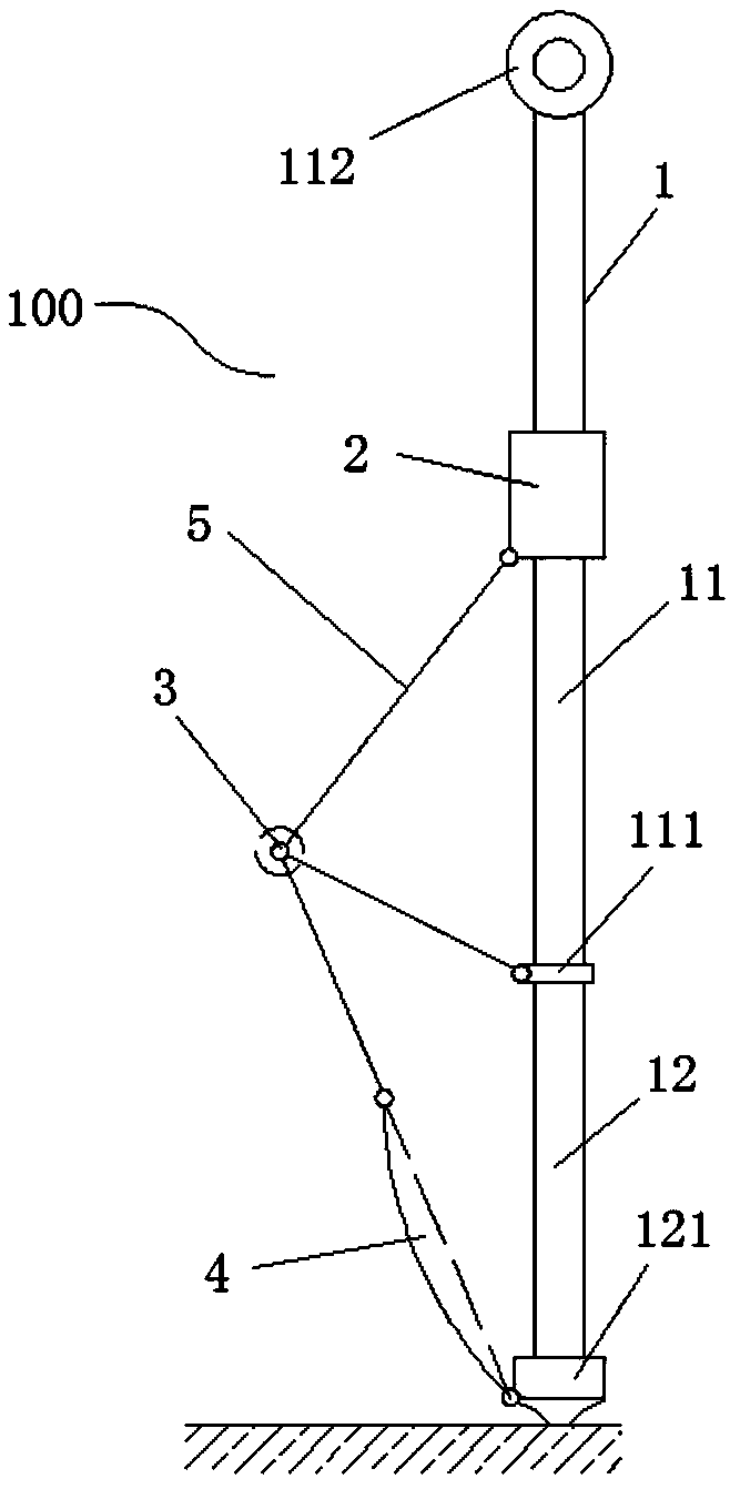
[0036] like figure 1 As shown, this embodiment provides a mechanical foot structure 100 for a robot, which mainly includes: a main body 1 of the mechanical foot, a slider 2 and a half-directional hinge 3 .

[0037] The main body 1 is a metal rod, which is divided into two connected sections, including a slide bar 11 and a leg bar 12. The surface of the slide bar 11 is smooth, and one end of the leg bar 12 is The other end of the sliding bar 11 and the leg bar 12 is provided with a first support part 121 ; the first support part 121 includes a foot cover provided at the end of the leg bar 12 .

[0038] The slider 2 is arranged on the slider 11 and is slidably connected to the slider 11. The junction of the slider 11 and the leg bar 12 is provided with a lower limit block 111 corresponding to the slider 2. An upper limit structure 112 is provided on the slide bar 11 corresponding to the lower limit block 111, and the slider 2 slides on the slide bar 11 section between the upper...

Embodiment 2

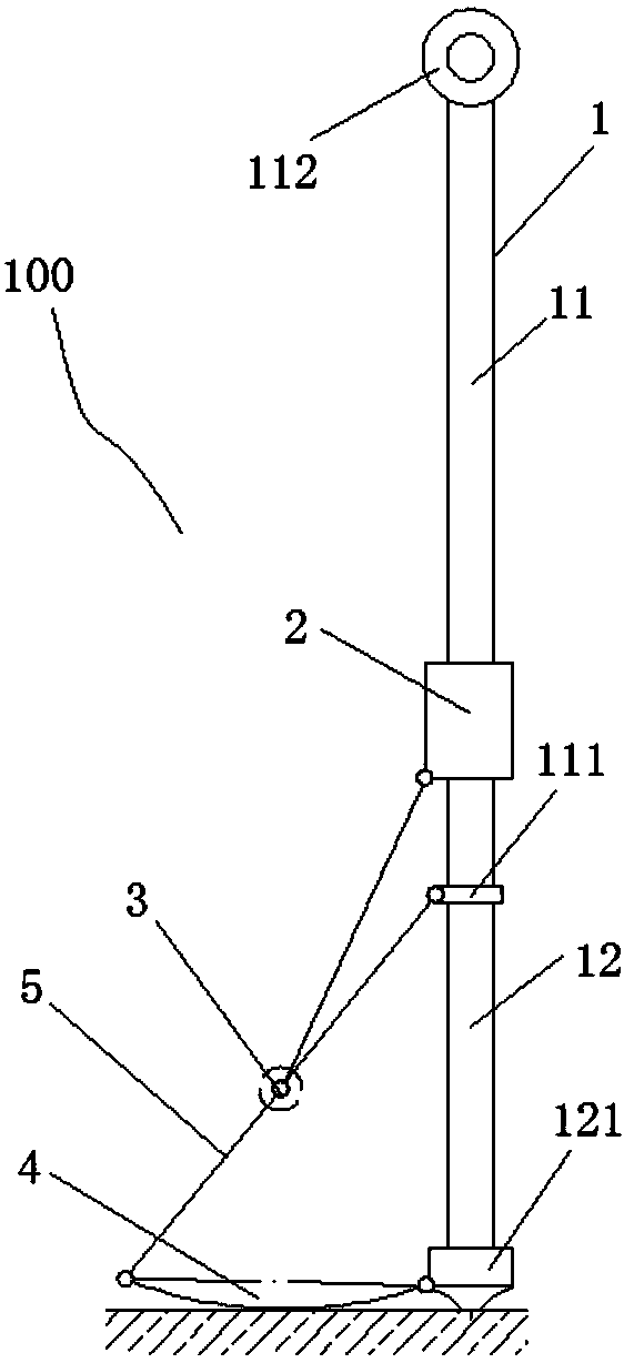
[0044]The same as in Embodiment 1 will not be repeated, in this embodiment, such as figure 2 As shown, the slider 2 is moved to the limit position along the lower limit block 111, at this time, the half-directional hinge 3 is connected with the lower limit block 111, and the half-directional hinge 3 is connected with the second supporting part. The connecting rod 5 of 4 is on the same straight line, and due to the tightening effect of the connecting rod 5 between the slider 2 and the half hinge 3, the disc is in a horizontal state, and the lowest point of the arc-shaped convex surface on the disc is The lowest point of the foot cover on the first supporting part 121 is on the same plane and touches the ground. At this time, the contact surface between the mechanical foot and the ground will gradually become larger, which is suitable for walking on soft ground. The second supporting part 4 can also be set in an oval or spherical shape to improve walking adaptability on soft gr...

Embodiment 3

[0046] The difference from Embodiment 2 is that the mechanical foot structure 100 in this embodiment is not installed on the robot, but on a structure with a certain buoyancy of its own, such as Image 6 The hull structure shown in 6.

[0047] In this embodiment, in order to facilitate the main body 1 rod of the mechanical foot to be arranged on the hull structure 6, the other end of the annular bushing provided on the upper limit structure 112 can be provided with an extension corresponding to the main body 1 rod (in the figure not shown), so as to facilitate the user's hand-held control; the mechanical foot structure 100 is set to a swingable form similar to a paddle through an annular bushing, so as to facilitate the mechanical foot to cooperate with the propulsion movement of the hull structure 6 in water. Further, the mechanical foot structure 100 can also be in the form of a mechanical arrangement, such as through the rotating shaft socketed with the annular bushing, and...


PUM


Abstract

The invention discloses a three-state mechanical foot structure. The three-state mechanical foot structure comprises a body, a slider and semi-directional hinge part and is characterized in that the body comprises a slide rod and a leg rod, and the leg rod is provided with a first support part; the slider is arranged on the slide rod, a lower limit block corresponding to the slider is arranged atthe joint of the slide rod and the leg rod, and the slide rod is provided with an upper limit structure corresponding to the lower limit block; the semi-directional hinge part comprises a plate body,the upper end face of the plate body is provided with a first hinge part, the lower end face of the plate body is provided with a second hinge part and a third hinge part, the first hinge part is hinged to the slider, the second hinge part is hinged to the lower limit block, and the third hinge part is hinged to the first support part by being hinged to a second support part. The three-state mechanical foot structure has the advantages that the an existing structure with the three-state mechanical foot structure can move on the hard ground and the soft ground and in water, and site limitationis avoided.

Description

technical field [0001] The invention belongs to the technical field of robot structure research, and in particular relates to a three-state mechanical foot structure capable of walking on hard ground, soft ground and water. Background technique [0002] With the development of science and technology, people's demand for robots is increasing, and the development of robots is gradually showing diversification; however, most of the robots in the existing technology are designed for specific conditions, so they can only be used in work in a single environment. The most common ones are underwater robots for underwater operations, which mainly rely on propellers; and land robots for operations on hard ground, which mainly rely on the replacement of foot structures or wheeled propulsion; Amphibious robots that can work and walk on land are very rare, and there are few cases of robots that can walk on soft areas. [0003] Therefore, it is of great significance to develop a robot t...

Claims


Application Information

Patent Timeline
IPC IPC(8): B62D57/032B63H1/02B63H1/36B63H16/08
CPCB62D57/032B63H1/02B63H1/36B63H16/08
Inventor 陈楷镟王祺博曾文锋王兴波
Owner FOSHAN UNIVERSITY
Why Eureka
Try Eureka