Eureka AIR delivers breakthrough ideas for toughest innovation challenges, trusted by R&D personnel around the world.

Winding machine with high automation degree

A kind of winding machine, high-level technology, applied in the field of machinery, can solve the problems of unreliable use, insufficient winding efficiency, easy to wear wire body, etc., to save time, improve the degree of winding automatic machine, and meet the needs of use Effect

Active Publication Date: 2018-09-04
JIANGNAN UNIV
View PDF9 Cites 2 Cited by
  • Summary
  • Abstract
  • Description
  • Claims
  • Application Information

AI Technical Summary

Problems solved by technology

[0002] A winding machine with a high degree of automation is a device that winds a linear object onto a specific workpiece. It is usually used for winding copper wires. Most of the wires wound by winding machines are enamelled copper wires (winding electronic and electrical products) Inductance coils), enamelled aluminum wires, textile wires (yarns and coils for winding textile machines), heating wires and solder wires, wires, cables, etc. for winding electric heating appliances, and the types of winding machines There are many types, which can be divided into general-purpose and special-purpose according to their uses; general-purpose-winding machines suitable for a variety of products, as long as the corresponding molds and instructions are replaced, they can correspond to the processing of different products; special-purpose-for A winding machine for a specific product. However, the existing winding machines with a high degree of automation cannot meet the needs of use. The winding efficiency is not high enough, and the wire body is easy to wear when cutting, extrusion, and fixing, so it is unreliable to use.

Method used


Image

  • Winding machine with high automation degree
  • Winding machine with high automation degree
  • Winding machine with high automation degree

Examples


Embodiment Construction

[0048] In order to make the above objects, features and advantages of the present invention more obvious and comprehensible, specific implementations of the present invention will be described in detail below in conjunction with the accompanying drawings.

[0049] In the following description, a lot of specific details are set forth in order to fully understand the present invention, but the present invention can also be implemented in other ways different from those described here, and those skilled in the art can do it without departing from the meaning of the present invention. By analogy, the present invention is therefore not limited to the specific examples disclosed below.

[0050] Second, "one embodiment" or "an embodiment" referred to herein refers to a specific feature, structure or characteristic that may be included in at least one implementation of the present invention. "In one embodiment" appearing in different places in this specification does not all refer to ...


PUM


Abstract

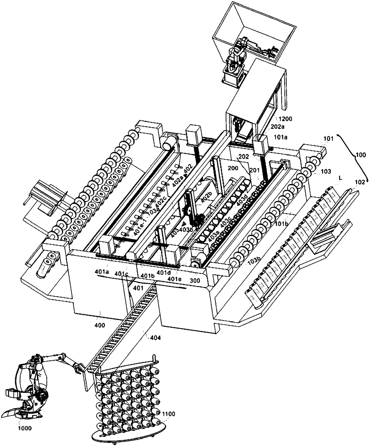
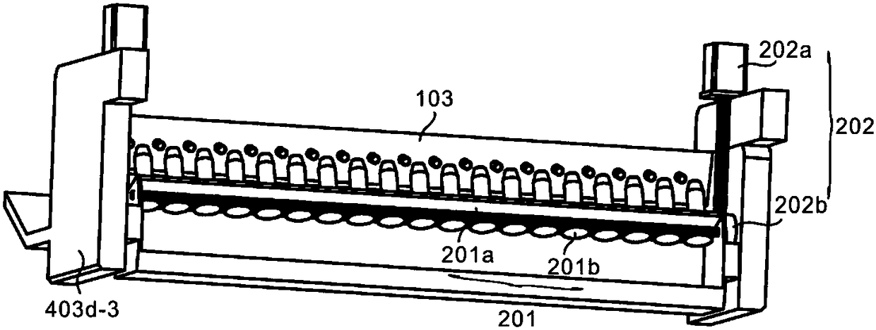
The invention discloses a winding machine with a high automation degree. The winding machine comprises a paying-off module, a take-up module, a tailoring module and a cylinder changing module, whereinthe paying-off module comprises a supporting unit, a pressing unit, a guide conveying unit and a first storing unit, the first storing unit and the pressing unit are arranged at one end of the supporting unit, the guide conveying unit is arranged on the supporting unit, the take-up module is arranged at the other end of the supporting unit and comprises a second storing unit and a power unit, thesecond storing unit is connected with the power unit, the tailoring module is arranged between a first guide wire part of the guide conveying unit and the second storing unit, and the cylinder changing module is arranged on one side of the take-up module. An upper cylinder module has a function of automatically feeding empty rolling cylinders and adjusting the empty rolling cylinders, a clampingpart can carry out clamping and storing beneficially, then the working efficiency of the winding and carrying device can be improved, the arranged storing units can stretch out and retract back, and thus the winding machine can adapt to storing of the empty rolling cylinders with different lengths or large winding cylinders.

Description

technical field [0001] The technical field of machinery that the present invention relates to particularly relates to a winding machine with a high degree of automation. Background technique [0002] A winding machine with a high degree of automation is a device that winds a linear object onto a specific workpiece. It is usually used for winding copper wires. Most of the wires wound by winding machines are enamelled copper wires (winding electronic and electrical products) Inductance coils), enamelled aluminum wires, textile wires (yarns and coils for winding textile machines), heating wires and solder wires, wires, cables, etc. for winding electric heating appliances, and the types of winding machines There are many types, which can be divided into general-purpose and special-purpose according to their uses; general-purpose-winding machines suitable for a variety of products, as long as the corresponding molds and instructions are replaced, they can correspond to the proces...

Claims


Application Information

Patent Timeline
IPC IPC(8): B65H54/54B65H54/24B65H57/14B65H54/70B65H67/04
CPCB65H54/24B65H54/54B65H54/70B65H57/14B65H67/0411B65H67/0417Y02P70/50
Inventor 傅佳佳金佳冰刘水平许波
Owner JIANGNAN UNIV
Why Eureka
Eureka Blog
Learn More