Electrical equipment heat treatment device

A heat treatment device and electrical equipment technology, applied in heat treatment furnaces, heat treatment equipment, furnaces, etc., can solve the problems of material drop, poor heat treatment effect, low production efficiency, etc., achieve uniform heat treatment, improve uniformity, and facilitate loading and unloading Effect

Inactive Publication Date: 2018-09-04
宗立武
View PDF2 Cites 2 Cited by
  • Summary
  • Abstract
  • Description
  • Claims
  • Application Information

AI Technical Summary

Problems solved by technology

The existing heat treatment device has uneven heat treatment, which easily leads to material deformation, poor heat treatment effect, and the loading and unloading process is cumbersome, the production efficiency is low, the hanging material is not stable, and it is easy to cause the material to fall and cause losses.

Method used

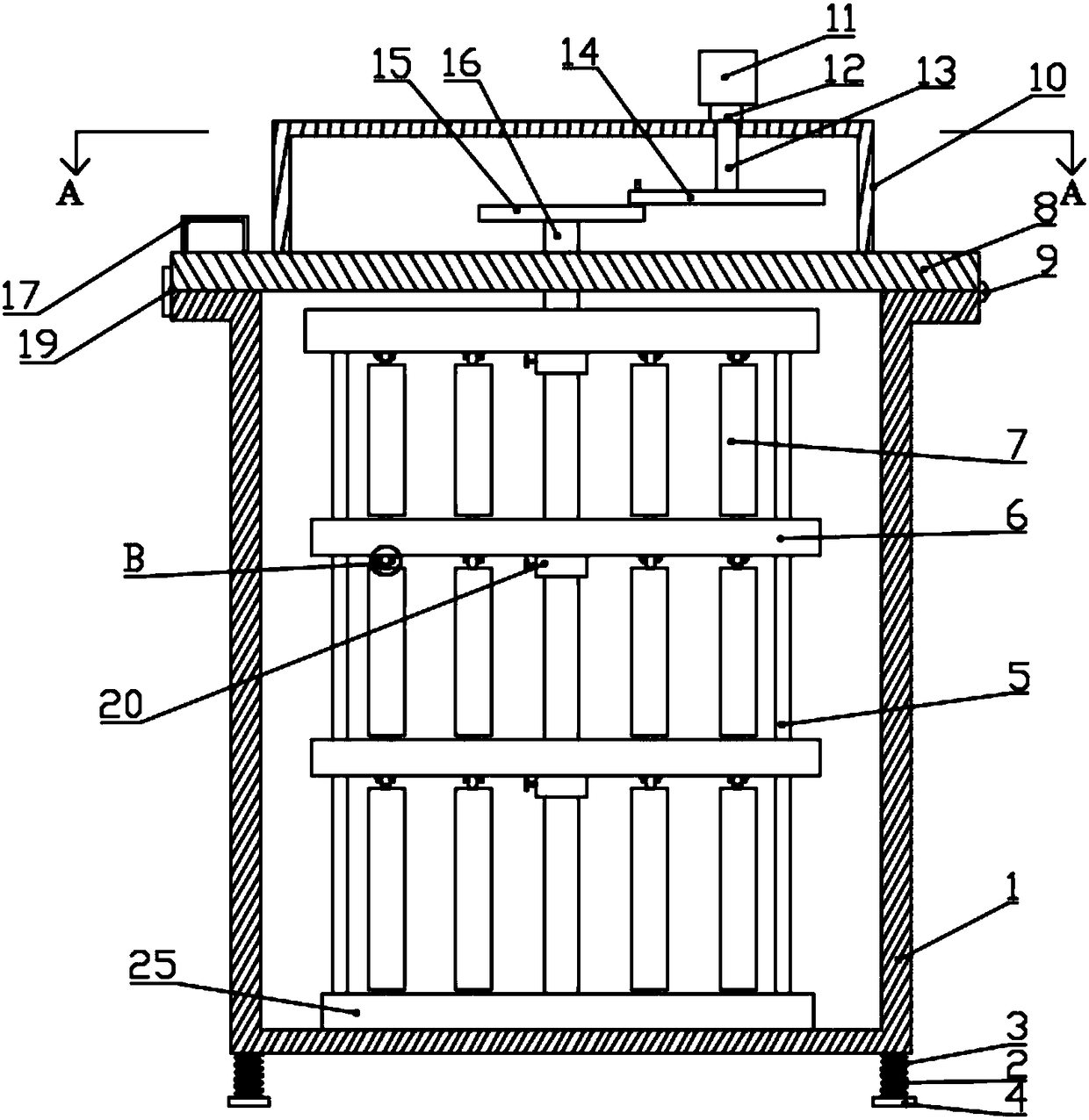
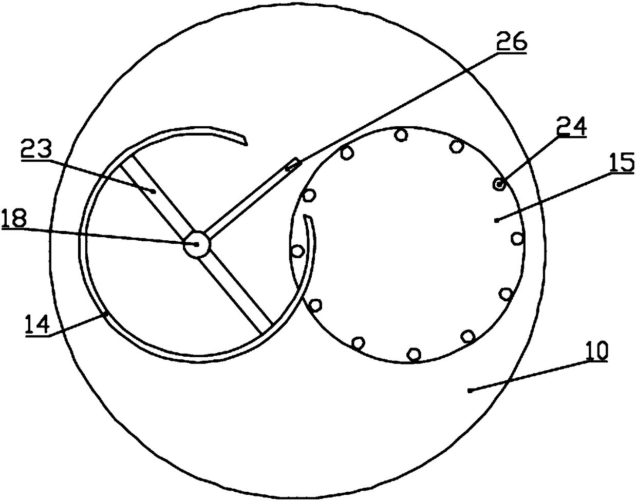
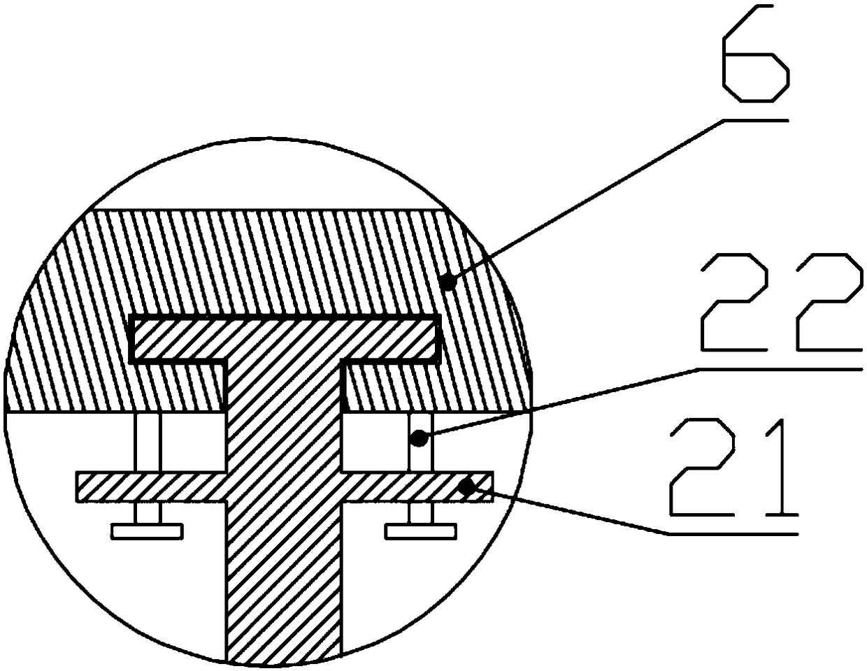

Image

  • Electrical equipment heat treatment device
  • Electrical equipment heat treatment device
  • Electrical equipment heat treatment device

Examples


Embodiment Construction

[0017] In describing the present invention, it should be understood that the terms "center", "longitudinal", "transverse", "upper", "lower", "front", "rear", "left", "right", " The orientations or positional relationships indicated by "vertical", "horizontal", "top", "bottom", "inner" and "outer" are based on the orientations or positional relationships shown in the drawings, and are only for the convenience of describing the present invention and Simplified descriptions, rather than indicating or implying that the device or element referred to must have a particular orientation, be constructed and operate in a particular orientation, and thus should not be construed as limiting the invention. In addition, the terms "first", "second", etc. are used for descriptive purposes only, and should not be understood as indicating or implying relative importance or implicitly specifying the quantity of the indicated technical features. Thus, a feature defined as "first", "second", etc. ...


PUM


Abstract

The invention discloses an electrical equipment heat treatment device. The electrical equipment heat treatment device comprises a furnace body, wherein a cover plate is arranged at the upper end of the furnace body; a power cover is arranged on the upper portion of the cover plate, and a coupler is arranged on the power cover; the upper end of the coupler is arranged at the output end of a motor,the other end of the coupler is arranged on a first rotating shaft, and the lower end of the first rotating shaft is arranged on a driving piece; the driving piece is matched with a driven disc, a second rotating shaft is arranged at the center of the driven disc, and material placing plates are arranged on the second rotating shaft; a guide rail is arranged on the outer side of the material placing plates, the bottom of the guide rail is arranged on a bottom plate, and the bottom of the second rotating shaft is rotationally arranged on the bottom plate; and fixing frames are arranged at the bottom of the material placing plates, material hanging frames are arranged on the material placing plates, and a device used for fixing the material hanging frames is arranged on the bottom of the material placing plates. The electrical equipment heat treatment device has the advantages of being simple in structure, convenient to use, uniform in heat treatment, convenient to feed and discharge, stable to hang piece, and stable in operation.

Description

technical field [0001] The invention relates to the technical field of electrical equipment processing, in particular to an electrical equipment heat treatment device. Background technique [0002] In the field of electrical equipment machining technology, it is often necessary to heat treat some materials with a certain shape, so the shape of the heat treated and tempered material is generally divided into rod shape, plate shape, ring shape, etc. At present, the device for processing plate-shaped materials is mainly divided into three parts: the surrounding support shaft and the hoisting device, the upper and lower square fixed support plates, and the lower end base plate. The existing heat treatment device has uneven heat treatment, which easily leads to material deformation, poor heat treatment effect, cumbersome loading and unloading process, low production efficiency, unstable hanging material, and easy loss of material falling. Contents of the invention [0003] The...

Claims


Application Information

Patent Timeline
Patent Type & Authority Applications(China)
IPC IPC(8): C21D1/25C21D9/00
CPCC21D1/25C21D9/0025
Inventor 宗立武
Owner 宗立武
Why Eureka
Try Eureka