Fe-BASED AMORPHOUS ALLOY, POWDER CORE USING THE SAME, AND COIL ENCAPSULATED POWDER CORE

a technology of amorphous alloys and powder cores, which is applied in the direction of transformers/inductances magnetic cores, inductances, etc., can solve the problems of insufficient reduction of amorphous alloys, insufficient utilization of characteristics of amorphous alloys, and insufficient reduction of core loss, so as to reduce the optimum heat treatment temperature of the core, reduce the loss of cores, and increase the effect of inductan

Active Publication Date: 2012-04-19
ALPS ALPINE CO LTD
View PDF6 Cites 7 Cited by
  • Summary
  • Abstract
  • Description
  • Claims
  • Application Information

AI Technical Summary

Benefits of technology

[0034]In the present invention, the optimum heat treatment temperature of the core can be decreased, the inductance can be increased, and the core loss can be reduced, and when mounting is performed in a power supply, power supply efficiency (η) can be improved.
[0035]In addition, in the coil encapsulated powder core according to the present invention, since the optimum heat treatment temperature of the Fe-based amorphous alloy can be decreased, the stress deformation can be appropriately reduced at a heat treatment temperature lower than a heat resistant temperature of the binding agent, and a magnetic permeability μ of the powder core can be increased; hence, by using an edgewise coil having a larger cross-sectional area of a conductor in each turn than that of a round wire coil, a desired high inductance can be obtained with a smaller turn number. As described above, in the present invention, since the edgewise coil having a large cross-sectional area of a conductor in each turn can be used as the coil, a direct current resistance Rdc can be decreased, and heat generation and copper loss can both be suppressed.

Problems solved by technology

Accordingly, in the past, the optimum heat treatment temperature was high, (the optimum heat treatment temperature−the heat treatment temperature T1) was increased, the stress deformation of the Fe-based amorphous alloy could not be sufficiently reduced; hence, the characteristics thereof could not be fully utilized, and the core loss could not be sufficiently reduced.

Method used


Image

  • Fe-BASED AMORPHOUS ALLOY, POWDER CORE USING THE SAME, AND COIL ENCAPSULATED POWDER CORE
  • Fe-BASED AMORPHOUS ALLOY, POWDER CORE USING THE SAME, AND COIL ENCAPSULATED POWDER CORE
  • Fe-BASED AMORPHOUS ALLOY, POWDER CORE USING THE SAME, AND COIL ENCAPSULATED POWDER CORE

Examples


examples

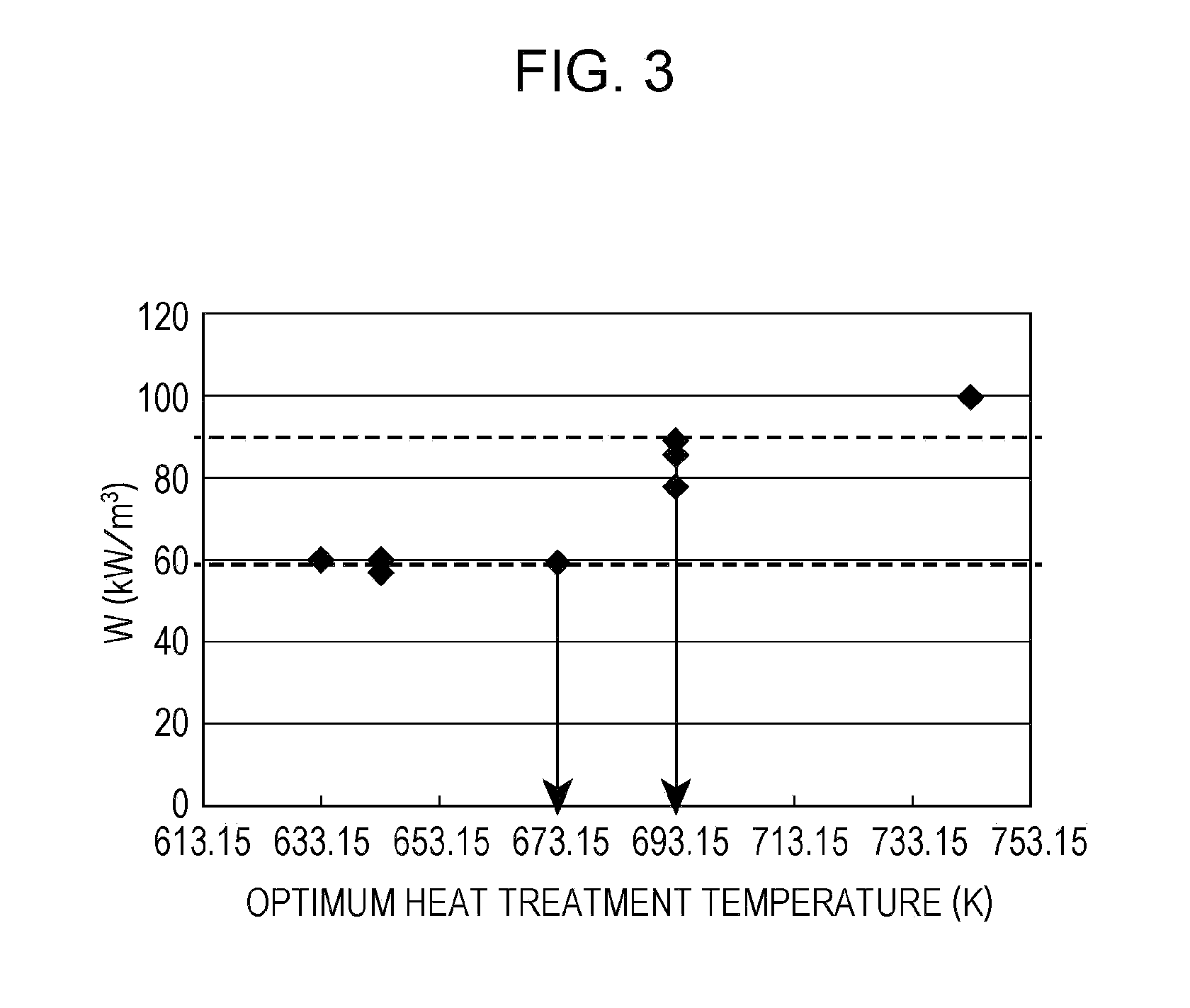
(Experiment to Obtain Relationship Between Optimum Heat Treatment Temperature and Glass Transition Temperature (Tg))

[0116]Fe-based amorphous alloys having respective compositions shown in the following Table 1 were manufactured. By a liquid quenching method, these alloys were each manufactured to have a ribbon shape.

[0117]In addition, Sample No. 1 is a comparative example and Sample Nos. 2 to 8 are examples.

[0118]It was confirmed by an X-ray diffractometer (XRD) that samples shown Table 1 were all amorphous. In addition, Curie temperature (Tc), the glass transition temperature (Tg), the crystallization starting temperature (Tx), and the melting point (Tm) were measured by a differential scanning calorimeter (DSC) (temperature rise rates for Tc, Tg, and Tx were each 0.67K / sec, and that for Tm was 0.33K / sec).

[0119]In addition, the saturation magnetization Is and the saturation mass magnetization σs shown in Table 1 (in appendix) were measured by a vibrating sample magnetometer (VSM).

[...


PUM

PropertyMeasurementUnit
Tg/aaaaaaaaaa
Tgaaaaaaaaaa
Tgaaaaaaaaaa

Abstract

An Fe-based amorphous alloy of the present invention has a composition formula represented by Fe100-a-b-c-x-y-z-tNiaSnbCrcPxCyBzSit, and in the formula, 0 at %≦a≦10 at %, 0 at %≦b≦3 at %, 0 at %≦c≦6 at %, 6.8 at %≦x≦10.8 at %, 2.2 at %≦y≦9.8 at %, 0 at %≦z≦4.2 at %, and 0 at %≦t≦3.9 at % hold. Accordingly, an Fe-based amorphous alloy used for a powder core and/or a coil encapsulated powder core having a low glass transition temperature (Tg), a high conversion vitrification temperature (Tg/Tm), and excellent magnetization and corrosion resistance can be manufactured.

Description

CLAIM OF PRIORITY[0001]This application is a Continuation of International Application No. PCT / JP2010 / 058028 filed on May 12, 2010, which claims benefit of Japanese Patent Application No. 2009-184974 filed on Aug. 7, 2009. The entire contents of each application noted above are hereby incorporated by reference.BACKGROUND OF THE INVENTION[0002]1. Field of the Invention[0003]The present invention relates to a Fe-based amorphous alloy applied, for example, to a powder core of a transformer, a power supply choke coil, or the like and a coil encapsulated powder core.[0004]2. Description of the Related Art[0005]Concomitant with recent trend toward a higher frequency and a larger current, a powder core and a coil encapsulated powder core, which are applied to electronic components and the like, are each required to have superior direct-current superposing characteristics, a low core loss, and a constant inductance in a frequency range up to MHz.[0006]Incidentally, a heat treatment is perfo...

Claims


Application Information

Patent Timeline
Patent Type & Authority Applications(United States)
IPC IPC(8): H01F1/01H01F27/02C22C45/02H01F27/24
CPCC21D6/00C21D2201/03C22C33/003C22C45/02C22C2200/02H01F27/255H01F41/0226H01F2017/048H01F1/15308C22C33/02C22C2202/02H01F1/153H01F1/26
Inventor TSUCHIYA, KEIKOKOSHIBA, HISATOKANEKO, KAZUYAABIKO, SEIICHIMIZUSHIMA, TAKAO
Owner ALPS ALPINE CO LTD
Why Eureka
Try Eureka