
Iron based nanocrystalline magnet core for large power inverter power source and production method

A technology of iron-based nanocrystals and inverter power supply, which is applied in the direction of transformer/inductor magnetic core, inductor/transformer/magnet manufacturing, circuit, etc. Temperature rise and other issues, to achieve good transverse magnetic field treatment effect, large magnetic induction anisotropy, low remanence induction intensity effect

Active Publication Date: 2009-07-08
ADVANCED TECHNOLOGY & MATERIALS CO LTD
View PDF3 Cites 29 Cited by
  • Summary
  • Abstract
  • Description
  • Claims
  • Application Information

AI Technical Summary

Problems solved by technology

The loss value of the magnetic core only accounts for 0.2 to 0.3% of the power of 10 to 15 kilowatts it transmits. Although the proportion is very small, the method provided by Japanese Patent Hei 3-205803 is used to protect the magnetic core or use surface spraying. The method of plastic or electrostatic spraying forms a resin or plastic protective layer and winds it into a transformer. During operation, the heat generated by the magnetic core will not be dissipated outward, causing the temperature rise of the transformer to be too high to be used. Therefore, it is provided to reduce the temperature rise of the transformer. Chinese patent ZL96106793.4 and ZL96244535.5 manufacturing method of soft magnetic core with mesh protection box
Although this method can reduce the temperature rise of the transformer and has good practicability, it has the disadvantages of exposing part of the magnetic core, easily damaging the slag, and affecting the insulation strength. Due to the structural characteristics of the protective box, the gap between the coil and the magnetic core is increased, resulting in an increase in the leakage inductance of the transformer and a decrease in efficiency.

Method used


Image

  • Iron based nanocrystalline magnet core for large power inverter power source and production method
  • Iron based nanocrystalline magnet core for large power inverter power source and production method
  • Iron based nanocrystalline magnet core for large power inverter power source and production method

Examples


Embodiment 1

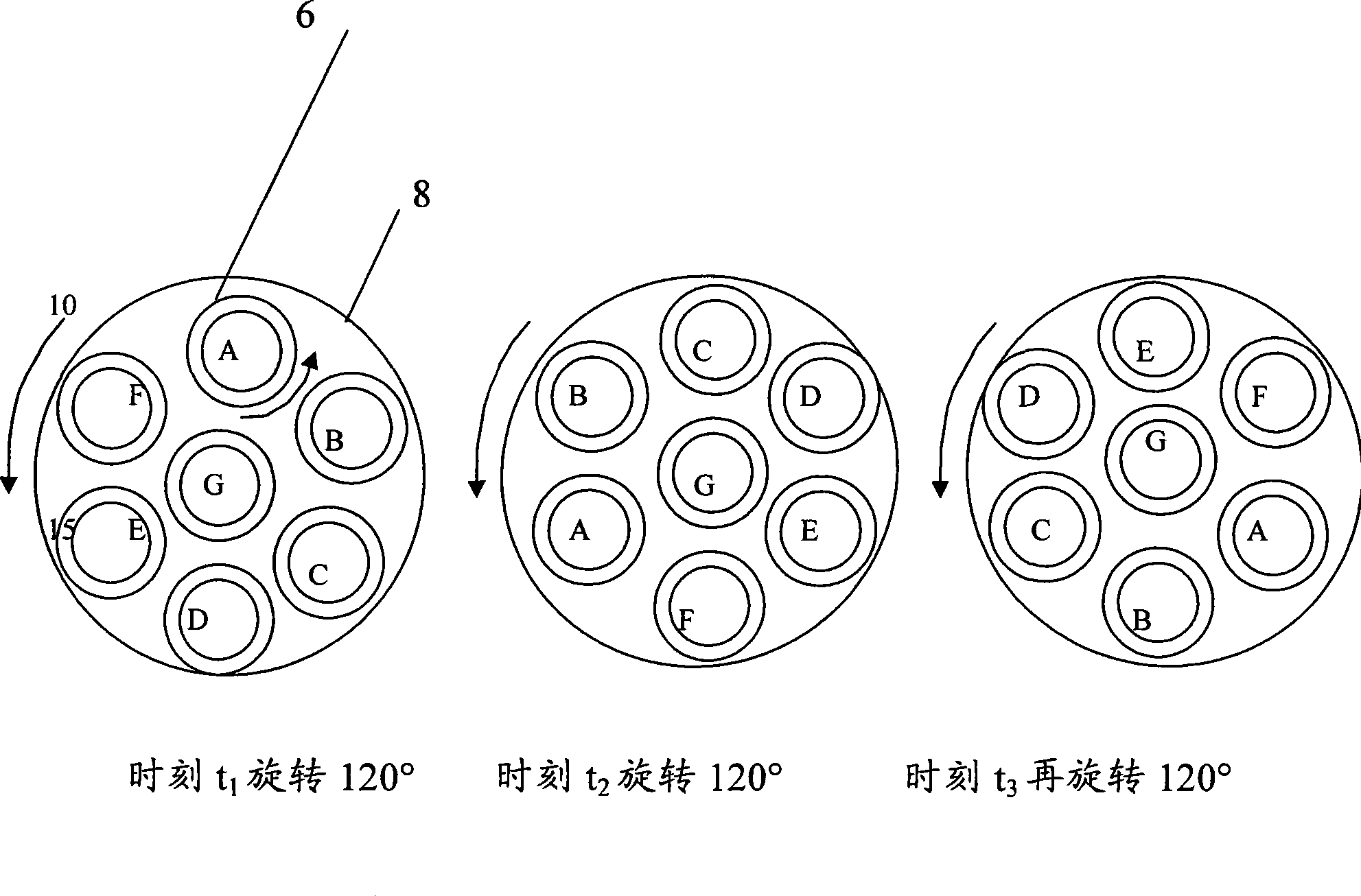
[0059] A master alloy whose composition is Fe82.5Cu1.2Co0.5Nb5.6Si8.7B1.5 (containing 0.018% Al) is made into a smooth strip with a thickness of 24 μm by a single roll method, a width of 30 mm, and a lateral thickness tolerance of less than 1 μm. Winding Put the ring-shaped magnetic core into a tubular transverse magnetic field furnace and hold it at 560°C for 1 hour. During the holding period, the magnetic core rotates 90° along the central axis every 5 minutes. Apply stress-free protective film evenly, put it into a protective box with mesh after curing, and measure the loss value with the attenuation oscillation transient analysis method, the loss P5 / 20k=21w / kg, the magnetic properties of the core are shown in Table 2.

[0060] Table 1 is a comparison table of the performance of the magnetic core of this embodiment and the transformer manufactured by the method of Chinese patent ZL96106793.4 after one hour of operation. It can be seen from Table 1 that a 315A inverter weld...

Embodiment 2

[0065] The master alloy whose composition is Fe82.9Cu1.29Co0.1Mo5.8Si8.0B1.9 (containing 0.01% Al and 0.008% Ti) is made into a bright thin strip with a thickness of 24 μm and a width of 40 mm by a single roll method, and is wound become The circular magnetic core is put into a tube-type transverse magnetic field furnace and kept at 530°C for 1 hour. During the heat preservation period, the magnetic core is rotated 90° along the central axis every 8 minutes. After the heat preservation is completed, it is cooled to room temperature with the furnace. The surface of the magnetic core is electrostatically sprayed to form a layer of epoxy resin film with a thickness of about 0.2mm on the surface. The magnetic properties of the magnetic core are measured by the attenuation oscillation transient analysis method, as shown in Table 2.

Embodiment 3

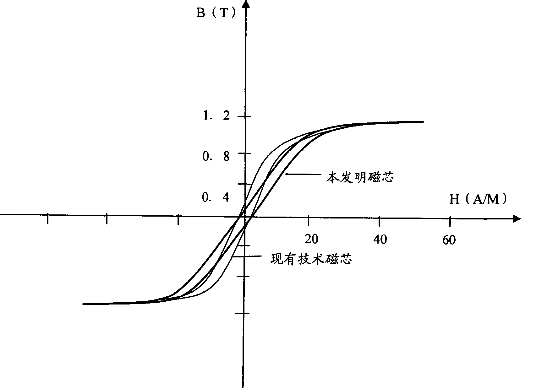
[0067] Other conditions are identical with embodiment 1, and composition is different from embodiment 1. The specific ingredients are shown in Table 2. Table 2 reflects the chemical composition of the present embodiment and comparative examples, the magnetic permeability μ, remanence ratio and loss value at f=20kHz, Bm=0.5T, where μ=μ 1 +iμ 2 .

[0068] Table 2

[0069]


PUM

PropertyMeasurementUnit
surface roughnessaaaaaaaaaa
loss valueaaaaaaaaaa
heightaaaaaaaaaa

Abstract

The invention relates to a soft magnetic core used for a high-power inverter power supply, and a manufacturing method thereof. The magnetic core is made of an Fe-based amorphous nano-crystalline belt material through winding , and comprises components according to weight percentages as follows: 81%-85% of Fe, 0.01%-5% of Co, 7%-9% of Si, 1.5%-2.5% of B, 1%-2% of Cu, 4%-7% of M, and 0.001%-0.04% of M', wherein M is one or more of Nb, Mo, V, W and Ta, and M' is at least one of Al and Ti. The magnetic core is subjected to anneal in a protective atmosphere or a vacuum; when in anneal, the position of the magnetic core in a furnace is movable or rotatable, a holding temperature is 520-600 DEG C, the holding time is 1-2 hours, and a temperature rise speed is 100 DEG C per hour. The magnetic core manufactured by adopting the method has lower loss, better manufacturing technique properties, and good soft magnetic characteristics; moreover, the downstream processing after the heat treatment is applicable to various technique methods.

Description

technical field [0001] The invention relates to a soft magnetic core for a high-power inverter power supply and a manufacturing method thereof, in particular to an iron-based nanocrystalline magnetic core with nanocrystalline and amorphous mixed structures and more excellent soft magnetic properties than the prior art. core and manufacturing method. Background technique [0002] High-power inverter power supply and switching power supply have been relatively mature and widely used in various fields. It has the advantages of small size, high efficiency, energy saving, material saving and environmental protection. [0003] Transformer core is an important part of high-power inverter power supply. It requires relatively high magnetic permeability, good thermal stability, and especially low loss. Because this kind of transformer is a power transmission component, when the frequency is high, the magnetic core per kilogram of weight needs to transmit 10-15 kilowatts of energy. T...

Claims


Application Information

Patent Timeline
Patent Type & Authority Applications(China)
IPC IPC(8): H01F1/147H01F1/20H01F27/25H01F41/02
Inventor 王立军陈文智王六一张宁娜宋翀旸
Owner ADVANCED TECHNOLOGY & MATERIALS CO LTD
Learn More