
Prefabricated prestress concrete frame beam-column joint with additionally-arranged steel bars and sleeves

A technology for precast concrete, beam-column joints, applied in building reinforcements, structural elements, building components, etc., can solve the problems of poor lap force transmission performance and joint ductility, complex on-site operations, poor economic indicators, etc. The effect of reducing the rib rate, ensuring the scope of development, and reducing the cost of the project

Inactive Publication Date: 2018-09-04
SOUTHEAST UNIV
View PDF5 Cites 7 Cited by
  • Summary
  • Abstract
  • Description
  • Claims
  • Application Information

AI Technical Summary

Problems solved by technology

[0004] For the above-mentioned connection structure, for the joint structure where the beam-column members are connected by steel member bolts, the on-site construction accuracy is required to be high, and the economic index is poor. The performance and ductility of joints are poor. For the structure in which the steel bars with hooks protruding from the end of the stepped corbels are anchored into the joint area, the steel bars at the bottom of the beam and the column bars in different directions will make more steel bars in the joint area, resulting in congestion and collision problems. , for the structure of adding bolts and anchor heads with short steel bars and directly anchoring the steel strands into the beam-column joint area, the on-site operation is more complicated and the construction is inconvenient

Method used


Image

  • Prefabricated prestress concrete frame beam-column joint with additionally-arranged steel bars and sleeves
  • Prefabricated prestress concrete frame beam-column joint with additionally-arranged steel bars and sleeves
  • Prefabricated prestress concrete frame beam-column joint with additionally-arranged steel bars and sleeves

Examples


Embodiment Construction

[0017] Below in conjunction with concrete implementation and with reference to accompanying drawing, the present invention will be further described:

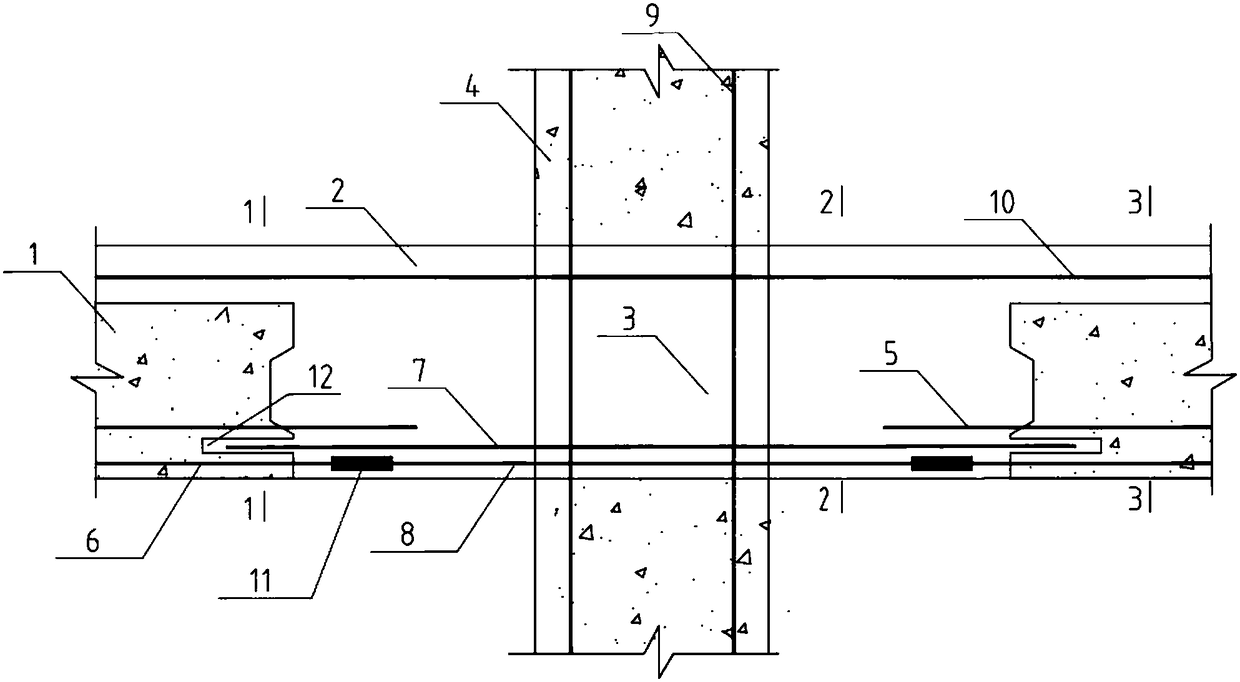
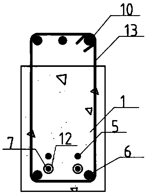
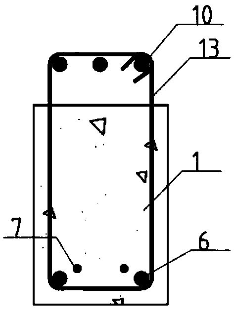
[0018] figure 1 It is a schematic diagram of the prefabricated prestressed concrete frame beam-column joint with additional steel bars and sleeves of the present invention, Figure 2-4 for corresponding to figure 1 Cross-sections of the beam-to-column joints in precast concrete frames. As shown in the figure, a prefabricated prestressed concrete frame beam-column joint with additional steel bars and sleeves mainly includes the post-casting area 3 of the beam-column joint, and precast concrete arranged at both horizontal ends of the post-casting area 3 of the beam-column joint Beam 1, precast concrete columns 4 arranged at the upper and lower ends of the post-cast area 3 of the beam-column node, and a composite beam cast-in-place area 2 arranged above the precast concrete beam 1 and the post-cast area 3 of the beam-column node...


PUM


Abstract

The invention discloses a prefabricated prestress concrete frame beam-column joint with additionally-arranged steel bars and sleeves. The prefabricated prestress concrete frame beam-column joint comprises a beam-column joint post-cast area, prefabricated concrete beams arranged on the horizontal two ends of the beam-column joint post-cast area, prefabricated concrete columns arranged at the upperend and the lower end of the beam-column joint post-cast area, and a superposed beam cast-in-situ area arranged above the prefabricated concrete beams and the beam-column joint post-cast area. Anti-seismic steel bars and the additionally-arranged steel bars are horizontally arranged on the lower portion of the beam-column joint post-cast area, the anti-seismic steel bars and stirrups in the beam-column joint post-cast area are connected, and the superposed beam cast-in-situ area and the beam-column joint post-cast area are cast into a whole. Longitudinal ordinary stress steel bars on the lowerside and the anti-seismic steel bars are connected through sleeves, and the additionally-arranged steel bars extend into bar inserting holes of the ends of the prefabricated concrete beams. Accordingto the prefabricated prestress concrete frame beam-column joint, the on-site construction difficulty is reduced, the size of a beam section and the steel using quantity are reduced, and the development and rotation performance of beam end plastic hinges and the anti-seismic performance such as integrity and ductility of the beam-column joint are ensured.

Description

technical field [0001] The invention relates to a prefabricated prestressed concrete frame beam-column joint with additional steel bars and sleeves, and belongs to the technical field of civil engineering prefabricated concrete structures. Background technique [0002] As the most widely used structural form in the field of construction engineering, the traditional cast-in-place reinforced concrete frame structure is mainly composed of beams, columns and beam-column joints. With the continuous improvement of the country's requirements for building industrialization and housing industrialization, the prefabricated prestressed assembly integral frame structure has been rapidly promoted because of its unique advantages. The advantages of this type of structural system include: adopting engineering mechanized production, easy to control product quality, good appearance quality and good durability of components; greatly saving the use of formwork and supports, and saving turnover...

Claims


Application Information

Patent Timeline
IPC IPC(8): E04B1/21E04B1/22E04C5/16
CPCE04B1/21E04B1/22E04C5/165
Inventor 冯健张骞陈耀
Owner SOUTHEAST UNIV
Learn More