In-situ centering clamping device and method for plate specimen of tensile fatigue tester

A technology of fatigue testing machine and flat sample, applied in the direction of measuring device, testing material strength by applying repetitive force/pulsation force, testing material strength by applying stable tension/pressure, etc., which can solve positioning ruler adjustment errors, scratches , erroneous test results and other issues to achieve the effect of ensuring consistency and accuracy, reducing manufacturing costs and improving reliability

Pending Publication Date: 2018-09-04
TIANJIN UNIV
View PDF8 Cites 7 Cited by
  • Summary
  • Abstract
  • Description
  • Claims
  • Application Information

AI Technical Summary

Problems solved by technology

This method will seriously affect the user's work efficiency for users with many specifications and a large amount of testing (such as the testing laboratory of a steel company).
In addition, when adjusting manually, it often occurs that the positioning ruler is adjusted incorrectly due to incorrect readings, resulting in the flat sample being tested under the wrong conditions and obtaining wrong test results.
[0008] 2. The positioning ruler is easily damaged
This situation is bound to have an inestimable impact on the accuracy and consistency of test r

Method used


Image

  • In-situ centering clamping device and method for plate specimen of tensile fatigue tester
  • In-situ centering clamping device and method for plate specimen of tensile fatigue tester
  • In-situ centering clamping device and method for plate specimen of tensile fatigue tester

Examples


Embodiment Construction

[0049] The in-situ centering and clamping device for the flat specimen of the tensile fatigue testing machine of the present invention will be described in detail below in conjunction with the embodiments and the accompanying drawings.

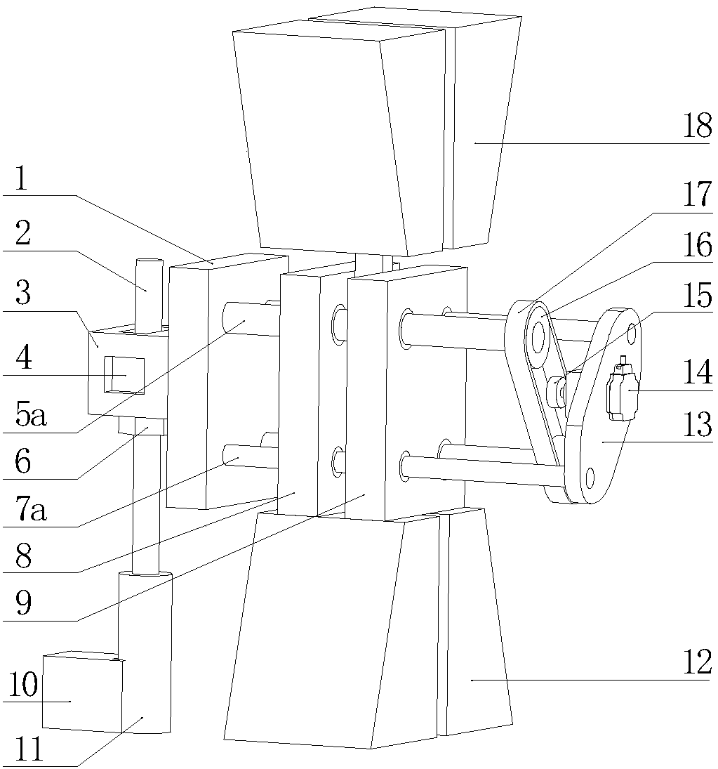
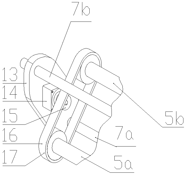
[0050] Such as figure 2 As shown, the in-situ centering clamping device of the flat sample of the tensile fatigue testing machine of the present invention includes an upper flat clamp block 18 and a lower flat clamp block 12 for clamping the upper and lower ends of the flat sample O. Between the flat clamping block 18 and the lower flat clamping block 12, a lateral clamping mechanism for clamping both sides of the flat plate sample O and a clamping drive mechanism for driving the lateral clamping mechanism are arranged, and the lateral clamping mechanism One side of the holding mechanism is fixedly connected with the height and lateral adjustment mechanism for vertical and lateral adjustment of the lateral clamping mechanism, and the lower pa...


PUM


Abstract

The invention discloses an in-situ centering clamping device and method for a plate specimen of a tensile fatigue tester. The device comprises upper flat clamping blocks and lower flat clamping blockswhich are used for clamping the upper and lower ends of the plate specimen, a side clamping mechanism used for clamping the two sides of the plate specimen and a clamping driving mechanism used for driving the side clamping mechanism are arranged between the upper flat clamping blocks and the lower flat clamping blocks, one side of the side clamping mechanism is fixedly connected with a height and transverse direction adjustment mechanism used for adjusting the side clamping mechanism vertically and transversely, and the lower part of the height and transverse direction adjustment mechanism is fixed to the middle plane of a clamping head of the tensile fatigue tester through a switch-type magnetic base. By means of the device, the coaxiality of the plate specimen on a clamp is guaranteed,the centering accuracy purpose during plate specimen installation of the tensile fatigue tester is achieved, and the consistency and the accuracy of a test result are ensured; moreover, based on thepremise that same functions are achieved, the device is conciser, the production cost is greatly reduced, and the reliability of the device is greatly improved.

Description

technical field [0001] The invention relates to a clamping device. In particular, it relates to an in-situ centering and clamping device and method for a flat sample of a tensile fatigue testing machine. Background technique [0002] The material universal testing machine is a device used for testing the mechanical properties of various materials. The basic mechanical performance indicators of materials, such as yield strength, tensile strength, elongation, elastic modulus, etc., can be obtained through tensile, compression, bending and other tests. As a kind of measuring equipment used for quality inspection, it has higher requirements on the quality of its products, and the accuracy of its test results must meet the requirements of relevant standards. For tensile testing machines, a crucial parameter that affects the accuracy of their test results is concentricity. There are two factors that affect the coaxiality. [0003] One is the structural rationality of the testi...

Claims


Application Information

Patent Timeline
IPC IPC(8): G01N3/04G01N3/08G01N3/32
CPCG01N3/04G01N3/08G01N3/32G01N2203/04G01N2203/0017G01N2203/0073
Inventor 陈刚李江华
Owner TIANJIN UNIV
Why Eureka
Try Eureka