
Dynamic power regulation and optimization method of impedance source direct-drive permanent magnet wind power generation system in grid voltage fault

A technology of wind power generation system and grid voltage, applied in wind power generation, electrical components, circuit devices, etc., can solve problems such as reducing system economy and reliability, increasing system cost and control difficulty, and improving safety and reducing software. The effect of hardware cost and fast dynamic response speed

Active Publication Date: 2018-09-04
HUNAN UNIV OF TECH
View PDF2 Cites 0 Cited by
  • Summary
  • Abstract
  • Description
  • Claims
  • Application Information

AI Technical Summary

Problems solved by technology

At present, the impedance source direct drive permanent magnet wind power generation system continues to use the fault ride-through method of three-phase uncontrollable +Boost and dual PWM topology when the grid voltage fails, and uses a crowbar circuit to balance the energy between the machine side and the grid side. This method greatly increases the system cost and control difficulty, and reduces the economy and reliability of the system

Method used


Image

  • Dynamic power regulation and optimization method of impedance source direct-drive permanent magnet wind power generation system in grid voltage fault
  • Dynamic power regulation and optimization method of impedance source direct-drive permanent magnet wind power generation system in grid voltage fault
  • Dynamic power regulation and optimization method of impedance source direct-drive permanent magnet wind power generation system in grid voltage fault

Examples


Embodiment Construction

[0042] In order to describe the present invention more specifically, the present invention will be further described below in conjunction with the accompanying drawings and embodiments.

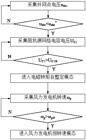
[0043] like figure 1 As shown, a dynamic power regulation and optimization method of a direct-drive permanent magnet wind power generation system with impedance sources (Z source, quasi-Z source, semi-quasi-Z source, etc.) under grid voltage faults, the steps include:

[0044] (1.1) Collect grid-connected point voltage u abc , judging u abc Is it less than the grid-connected point preset voltage u abc * , if u abc abc * , jump to step (1.2);

[0045] (1.2) Acquisition of impedance source network capacitance voltage U C1 , judging U C1 Is it greater than the impedance source network capacitance threshold voltage U C1N , if U C1 >U C1N , jump to step (1.3);

[0046] (1.3) Open the electromagnetic torque self-tuning mode of the impedance source direct drive permanent magnet wind pow...


PUM


Abstract

The invention discloses a dynamic power regulation and optimization method for an impedance source direct-drive permanent magnet wind power generation system in a grid voltage fault. The dynamic powerregulation and optimization method includes: collecting a grid-connected point voltage U<abc>, and determining whether the U<abc> is less than a grid-connected preset voltage U<abc*>; acquiring an impedance source network capacitor voltage U<C1>, and determine whether the U<C1> is greater than an impedance source network capacitance threshold voltage U<C1N>; allowing the impedance source direct-drive permanent magnet wind power generation system to enter an electromagnetic torque self-tuning mode if Uabc<Uabc* and U<C1> > U<C1N>, obtaining an impedance source network inductor current set value I<L*> according to a drop state of the grid voltage; acquiring the wind turbine speed omega g, and determining whether the omega g exceeds the rated speed omega gN of the wind turbine; and adjustingthe pitch angle to make the impedance source direct-drive permanent magnet wind power system enter a constant speed mode if omega g> omega gN. The invention can avoid the Crowbar circuit, simplifiesthe system structure, and improves the response speed and the stability of the system.

Description

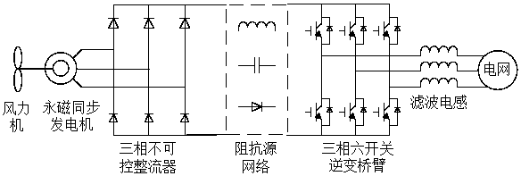
technical field [0001] The invention belongs to the field of grid-connected control of wind power generation, and in particular relates to a dynamic power adjustment and optimization method of an impedance source direct-driven permanent magnet wind power generation system under grid voltage failure. Background technique [0002] Impedance source (Z source, quasi-Z source, semi-quasi-Z source, etc.) direct-drive permanent magnet wind power generation system has the advantages of single-stage control, allowing the inverter bridge arm to pass through, and no need to insert dead time. In order to further improve the reliability of grid connection And reduce system cost provides a new way of thinking. At present, when the grid voltage fails, the impedance source direct drive permanent magnet wind power generation system continues to use the fault ride-through method of three-phase uncontrollable +Boost and dual PWM topology, and uses a crowbar circuit to balance the energy betwee...

Claims


Application Information

Patent Timeline
Patent Type & Authority Applications(China)
IPC IPC(8): H02J3/38
CPCH02J3/386H02J2203/20Y02E10/76
Inventor 张阳程谆
Owner HUNAN UNIV OF TECH
Learn More