Permanent magnet motor rotor and motor

A permanent magnet motor and rotor technology, applied in the direction of magnetic circuit rotating parts, magnetic circuits, electric components, etc., can solve the problems of unfavorable permanent magnet heat dissipation, eddy current loss, and reduce motor efficiency, so as to avoid the performance reduction of permanent magnets.

Inactive Publication Date: 2018-09-04
深圳派赛科技有限公司
View PDF8 Cites 3 Cited by
  • Summary
  • Abstract
  • Description
  • Claims
  • Application Information

AI Technical Summary

Problems solved by technology

[0002] The rotor of high-speed permanent magnet motor usually adopts sintered aluminum-iron-boron permanent magnet. The permanent magnet material can withstand relatively large compressive stress, but it can only withstand tensile stress below 100MPa, and its tensile strength is generally lower than one-tenth of the compressive strength. 1. Therefore, permanent magnets need protective measures to overcome the strong centrifugal force generated by high-speed rotating permanent magnets. The current method of protecting permanent magnets is to add high-strength non-magnetic protective sleeves outside the permanent magnets. The permanent magnets and protective sleeves use interference Cooperate, but the carbon fiber protective cover is a poor conductor of heat, which is not conducive to the heat dissipation of the permanent magnet, while the metal mesh protective cover has a good heat dissipation effect, but the metal mesh protective cover will produce eddy current loss and reduce the efficiency of the motor

Method used


Image

  • Permanent magnet motor rotor and motor
  • Permanent magnet motor rotor and motor
  • Permanent magnet motor rotor and motor

Examples


Embodiment Construction

[0030] In order to make the technical problems solved by the present invention, the technical solutions adopted and the technical effects achieved clearer, the technical solutions of the embodiments of the present invention will be further described in detail below in conjunction with the accompanying drawings. Obviously, the described embodiments are only the technical solutions of the present invention. Some, but not all, embodiments. Based on the embodiments of the present invention, all other embodiments obtained by those skilled in the art without creative efforts fall within the protection scope of the present invention.

[0031] In the description of the embodiments of the present invention, the terms "upper", "lower", "left", "right", "front", "rear", "inner", "outer", "top", "bottom", The orientation or positional relationship indicated by "horizontal", "vertical", etc. is based on the orientation or positional relationship shown in the drawings, and is only for the c...


PUM


Abstract

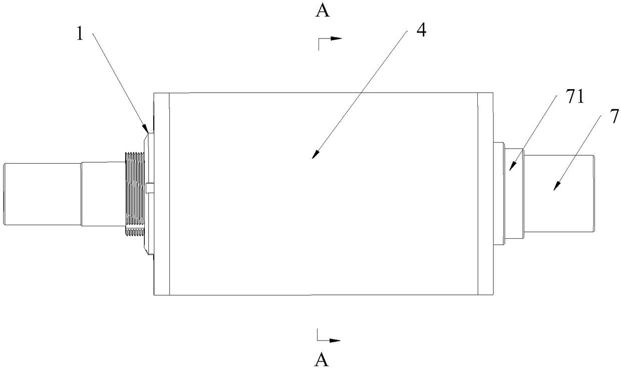
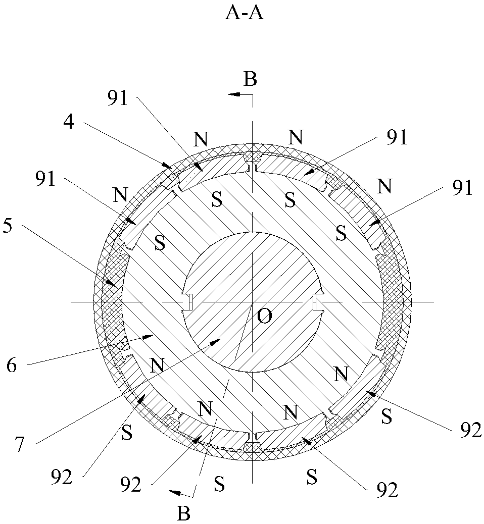
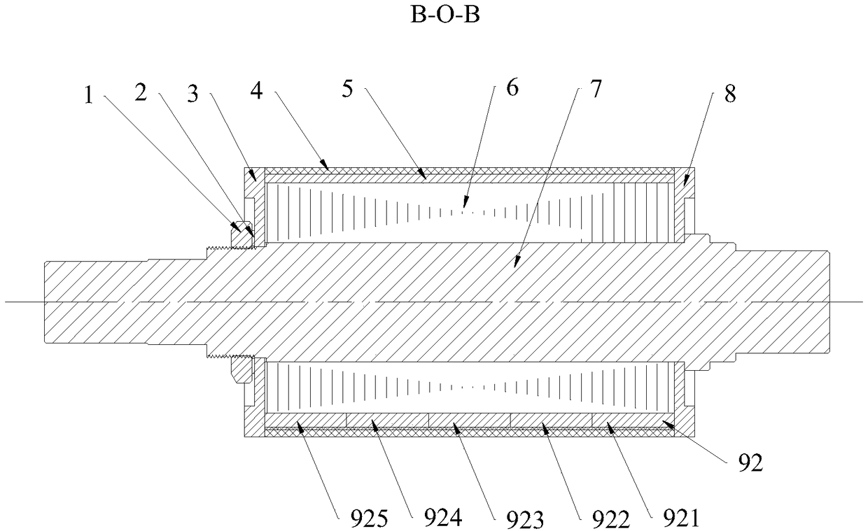
The invention discloses a permanent magnet motor rotor and a motor. The permanent magnet motor rotor comprises a rotor shaft, a rotor iron core, two magnetic poles and a sleeve, wherein the rotor ironcore sleeves the outside the rotor shaft, and a plurality of dovetail grooves are axially formed in the outer surface of the rotor iron core; the magnetic poles are respectively a north pole and a south pole and are symmetrically arranged on the outer surface of the rotor iron core, each magnetic pole comprises at least two permanent magnets, the cross sections of the permanent magnets are matched with the cross sections of the dovetail grooves, and the permanent magnets are embedded into the dovetail grooves; and the sleeve sleeves the periphery of the rotor iron core, and a gap between thesleeve and the rotor iron core is filled with epoxy resin. According to the permanent magnet motor rotor, the permanent magnets can be protected, and the good heat dissipation function of the permanent magnets and the good efficiency of the motor can be guaranteed.

Description

technical field [0001] The invention relates to the technical field of motors, in particular to a permanent magnet motor rotor and a motor. Background technique [0002] The rotor of high-speed permanent magnet motor usually adopts sintered aluminum-iron-boron permanent magnet. The permanent magnet material can withstand relatively large compressive stress, but it can only withstand tensile stress below 100MPa, and its tensile strength is generally lower than one-tenth of the compressive strength. 1. Therefore, permanent magnets need protective measures to overcome the strong centrifugal force generated by high-speed rotating permanent magnets. The current method of protecting permanent magnets is to add high-strength non-magnetic protective sleeves outside the permanent magnets. The permanent magnets and protective sleeves use interference Cooperate, but the carbon fiber protective cover is a poor conductor of heat, which is not conducive to the heat dissipation of the perm...

Claims


Application Information

Patent Timeline
Patent Type & Authority Applications(China)
IPC IPC(8): H02K1/27H02K9/22
CPCH02K1/276H02K9/22
Inventor 曾强
Owner 深圳派赛科技有限公司
Why Eureka
Try Eureka