Printing ink cartridge

A technology of ink cartridges and ink chambers, which is applied in the field of electronic products, and can solve problems such as the inability to solve the problem of residual ink, the reduction of ink capacity, etc.

Inactive Publication Date: 2018-09-07
MAIBO HIGH POLYMER MATERIAL NINGBO
View PDF10 Cites 0 Cited by
  • Summary
  • Abstract
  • Description
  • Claims
  • Application Information

AI Technical Summary

Problems solved by technology

This kind of ink cartridge reduces the amount of residual ink as a whole, but it still cannot solve the problem of residual ink in the lower layer of high-absorption ink storage material. At the same time, the ink capacity of the ink cartridge will be greatly reduced after the ink storage material is filled.

Method used


Image

  • Printing ink cartridge
  • Printing ink cartridge
  • Printing ink cartridge

Examples


Embodiment 1

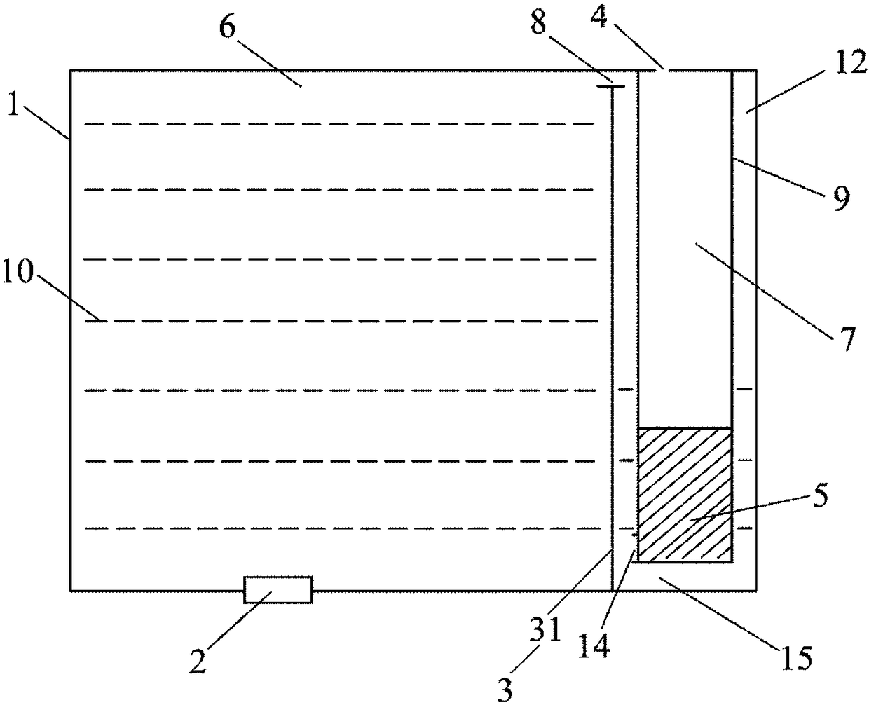
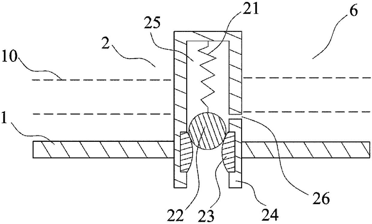
[0086] see Figure 1 to Figure 1B As shown, in the first specific embodiment of the present invention, the printing ink cartridge of the present invention includes a housing 1, an ink outlet device 2, a first partition wall 3, a first air guide channel 4, a gas-liquid exchange device 5, and a buffer chamber 7. The first communication channel 8 and the buffer chamber 9, the first partition wall 3 is set in the inner cavity of the housing 1 so as to divide the inner cavity of the housing 1 into the ink chamber 6 and the communication chamber 12, and the ink outlet device 2 is arranged in the The bottom of the ink chamber 6, the first communication channel 8 is arranged between the first partition wall 3 and the top of the housing 1 so as to communicate with the ink chamber 6 and the communication chamber 12, the buffer chamber 9 is arranged in the communication chamber 12, and the buffer chamber 9 An opening 14 is provided, and the opening 14 communicates with the first communic...

Embodiment 2

[0092] see figure 2 and Figure 2A As shown, the structure and working principle of the second embodiment of the present invention are similar to those of embodiment 1, the difference is that: the first communication channel 8 is arranged in the upper part of the vertical partition wall 31; the opening 14 is arranged at the bottom of the buffer chamber 9 and There is a gap 15 between the bottom of the buffer chamber 9 and the bottom of the communication chamber 12; the side of the buffer chamber 9 away from the first partition wall 3 is a part of the side of the communication chamber 12 away from the first partition wall 3, that is, a shared side, the maximum distance between the outer wall of the buffer chamber 9 and the inner wall of the communication chamber 12 is 0.5 millimeters; the core body 54 of the gas-liquid exchange device 5 is a single piece, which is a nylon 6 cylinder with convex ribs, and directly on the nylon 6 A capillary channel 40 is established in the mid...

Embodiment 3

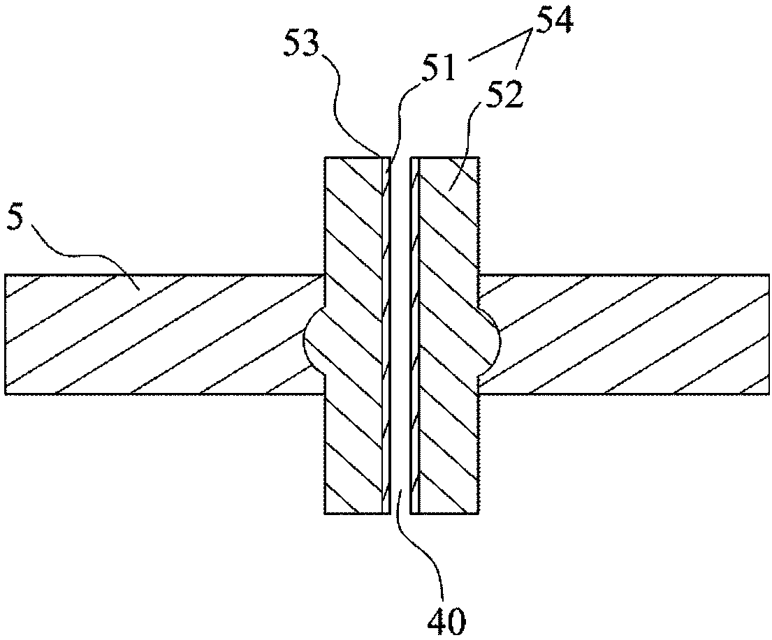
[0095] see Figure 3 to Figure 3B As shown, the third embodiment of the present invention is similar in structure and working principle to Embodiment 1, the difference is that: the first partition wall 3 includes a vertical partition wall 31 and a transverse partition wall 32, and the vertical partition wall 31 and the transverse partition wall 32 are connected to each other and are respectively connected to the inner wall of the housing 1; the two sides of the buffer chamber 9 are respectively a part of the two sides of the communicating chamber 12, that is, sharing both sides, the maximum distance between the outer wall of the buffer chamber 9 and the inner wall of the communicating chamber 12 is 0.1 mm; the first core 51 of the core 54 of the gas-liquid exchange device 5 is a ceramic cylinder with a diameter of 3 mm, and the second core 52 is integrally formed with other parts of the gas-liquid exchange device 5. For clarity, use The dotted line outlines part of the outline...


PUM

PropertyMeasurementUnit
lengthaaaaaaaaaa
thicknessaaaaaaaaaa
lengthaaaaaaaaaa

Abstract

The invention provides a printing ink cartridge, which is characterized in that a first partition wall divides an inner cavity of a shell into an ink cavity and a communicating cavity, the ink cavityand the communicating cavity are communicated through a first communicating channel, a buffer cavity is arranged in the communicating cavity, an opening of the buffer cavity is communicated with the first communicating channel through the communicating cavity, a buffer chamber and an air-liquid exchange device are arranged in the buffer cavity, the buffer chamber is located above the air-liquid exchange device, a first air guiding channel is arranged in the shell and communicates the outside air and the buffer chamber, the air-liquid exchange device is provided with a capillary channel, and the buffer chamber is communicated with the opening through the capillary channel. The printing ink cartridge is stable in performance, simple in structure, smooth in printing, large in ink capacity andless in residual ink and reduces the waste and environmental pollution.

Description

technical field [0001] The invention relates to the technical field of electronic products, in particular to the technical field of printing, and specifically refers to a printing ink cartridge. Background technique [0002] Inkjet printing is a relatively mature and widely used printing technology. Whether bubble or piezoelectric printing technology is used, the inkjet printing system generally needs to use a certain method to stably and controllably transport the liquid medium to be printed. to the print head. The commonly used method is to create a certain negative pressure in the ink cartridge, the ink in the ink cartridge is transported to the print head under the action of the suction force of the print head during printing, and at the same time, the negative pressure can effectively keep the ink in the ink cartridge without leakage . [0003] Various methods can be used to create the negative pressure in the ink cartridge, for example, using a mechanical valve to cr...

Claims


Application Information

Patent Timeline
Patent Type & Authority Applications(China)
IPC IPC(8): B41J2/175B22F3/22
CPCB22F3/22B41J2/175B41J2/17513B22F3/225B33Y30/00B41J2/1752
Inventor 王立平周兴夫王立娟
Owner MAIBO HIGH POLYMER MATERIAL NINGBO
Why Eureka
Try Eureka