Device for suction and decantation of a crankcase gas and associated installation

A crankcase and equipment technology, which is applied in the field of motor crankcase gas recovery and processing systems, can solve the problems of the lower motor and the upper motor being heavy, and achieve the effects of saving efficiency gains, improving discharge capacity, and saving space

Active Publication Date: 2018-09-07
AKWEL SA
View PDF5 Cites 0 Cited by
  • Summary
  • Abstract
  • Description
  • Claims
  • Application Information

AI Technical Summary

Problems solved by technology

However, these are added inside the gas recovery and treatment unit, so they are slightly bulkier for the lower and upper motors

Method used


Image

  • Device for suction and decantation of a crankcase gas and associated installation
  • Device for suction and decantation of a crankcase gas and associated installation
  • Device for suction and decantation of a crankcase gas and associated installation

Examples


Embodiment Construction

[0051] The elements common to all embodiments of the suction and decanting apparatus 1 according to the invention are described below.

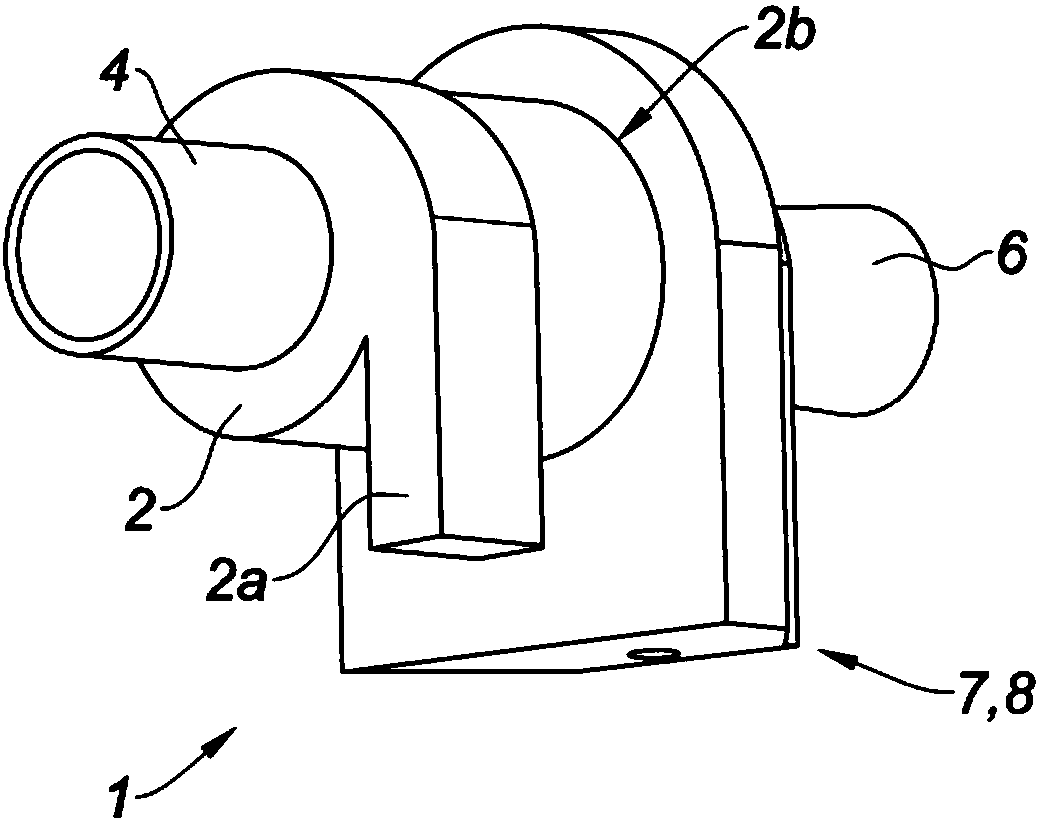
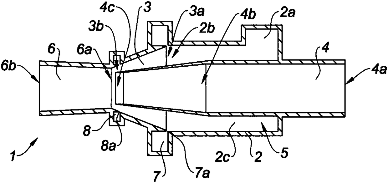
[0052] as in Figure 1 to Figure 9 and Figure 13 As exemplified in , the crankcase gas suction and decanting device 1 according to the invention comprises a crankcase gas collection cylinder 2 having a cylinder inlet 2a and a cylinder outlet 2b, said cylinder inlet 2a being shaped as a cut The cylinder inlet 2 a is arranged tangentially to the cylinder 2 to deliver crankcase gases.

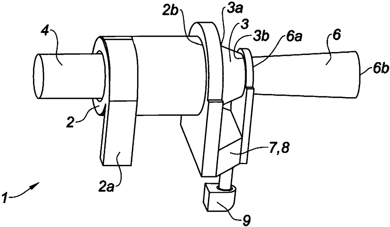
[0053] Furthermore, the suction and decanting device 1 comprises a first conical portion 3 comprising a first end 3a and a second end 3b arranged at the cylinder outlet 2b. as in image 3 and Figure 9 As clearly shown in , the first conical portion 3 converges from its first end 3a towards its second end 3b.

[0054] as in image 3 and Figure 9 in and in figure 1 , figure 2 , Figure 4 to Figure 8 and Figure 13 As shown in , the suction and decant...


PUM


Abstract

The invention discloses a device for suction and decantation of a crankcase gas and associated installation. The subject of the invention is a crankcase gas suction and decanting device (1) comprisingat least a combustion gas and engine oil, The suction and decanting device (1) comprising a crankcase gas collecting cylinder (2) comprising a cylinder inlet (2a) shaped to supply a crankcase gas anda cylinder outlet (2b) arranged tangentially to the cylinder (2); a first conical portion (3) comprising a first end (3a) and a second end (3b), the first end (3a) being arranged at the cylinder outlet (2b), the first conical portion (3) being convergent from its first end (3a) to its second end (3b), characterized in that the suction and decanting device (1) further comprises a second conical portion (6) having a first end (6a) and a second end (6b), the first end (6a) of the second conical portion (6) being positioned opposite the second end (3b) of the first conical portion (3), the secondconical portion (6) being divergent from its first end (6a) towards its second end (6b).

Description

technical field [0001] The present invention relates to the technical field of motor crankcase gas recovery and treatment systems having the introduction of air into the motor crankcase also known as "positive crankcase ventilation" and its acronym is a PCV. The invention preferably applies to vehicles equipped with such a crankcase gas recovery system that introduces air into the motor crankcase. Background technique [0002] In this application, the term "crankcase gases" refers to motor combustion gases mixed with small amounts of motor oil particles released from the motor pistons and cylinders. In operation, this combustion gas mixes with oil particles in the hermetically sealed lower motor. When there is too much crankcase gas formed, the pressure of the lower motor will rise which can cause operational problems of the motor, leaks etc. which can lead to motor failure. The term "lower motor" refers to the lower part of the motor, typically including the crankshaft, ...

Claims


Application Information

Patent Timeline
Patent Type & Authority Applications(China)
IPC IPC(8): F01M13/04
CPCF01M13/04F01M2013/0427F01M13/022F04F5/16F01M2013/026F01M2013/0488B01D45/12B04C3/06F04F5/20F04F5/46
Inventor 帕斯卡·盖里阿德里安·厄斯塔什卢多维克·塞吕里耶
Owner AKWEL SA
Why Eureka
Try Eureka