Electric vehicle gear shifting mechanism

A technology of shifting mechanism and electric vehicle, applied in the direction of transmission components, mechanical equipment, vehicle parts, etc., can solve the problems of high installation accuracy requirements, difficult to achieve the best efficiency point, large reduction ratio span, etc., to eliminate the control system. Damage, easy shifting, avoid the effect of tooth punching

Inactive Publication Date: 2018-09-07
如皋市招财牛车业有限公司
View PDF4 Cites 0 Cited by
  • Summary
  • Abstract
  • Description
  • Claims
  • Application Information

AI Technical Summary

Problems solved by technology

[0003] 1) The reduction ratio span between each gear is large, and the reduction ratio is about 2; when the reduction ratio span is too large, there will be a large impact force when shifting gears, resulting in the instantaneous maximum current, which is easy to cause damage to the control system
[0004] 2) The two-speed transmission mechanism transmits power through the shaft, and the shaft must bear both torque and weight. Therefore, the installation accuracy of the shaft is quite high, and a slight deviation will cause the motor shaft to break
[0005] 3) The two-speed transmission mechanism is three-stage deceleration regardless of high-speed gear or low-speed gear, and it is difficult to achieve the best efficiency point (output power divided by input power) during high-speed operation
[0006] 4) The shifting is controlled by the electromagnet, since the electromagnet will work all the time, this will inevitably cause energy waste

Method used


Image

  • Electric vehicle gear shifting mechanism
  • Electric vehicle gear shifting mechanism
  • Electric vehicle gear shifting mechanism

Examples


Embodiment Construction

[0027] Below in conjunction with accompanying drawing and embodiment the present invention will be further described:

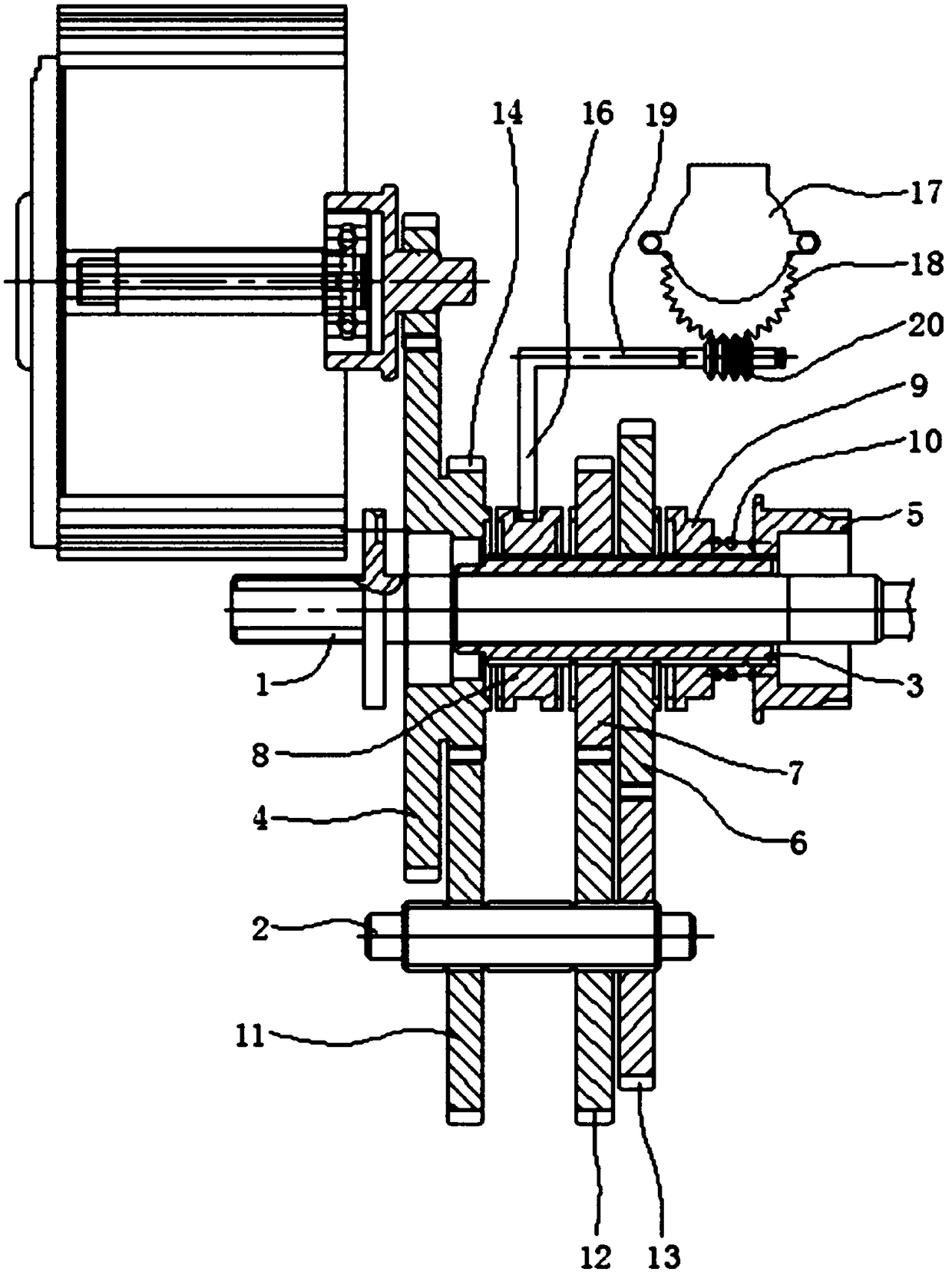
[0028] Such as figure 1 As shown, the main shaft 1 connected with the electric vehicle body is fixed, the main shaft 1 is parallel to the auxiliary shaft 2, and the auxiliary shaft 2 can rotate freely. A transmission sleeve 3 is sheathed on the main shaft 1 , and the transmission sleeve 3 can rotate relative to the main shaft 1 . Described transmission shaft sleeve 3 is as shown in the figure the left end of peripheral empty sleeve third gear 4, the right end of this third gear 4 is provided with secondary deceleration driving gear 14, secondary deceleration driving gear 14 and third gear 4 can be an integral structure, It can also be a split structure fixed together. The right end of the transmission shaft sleeve 3 is connected with the output spline sleeve 5, the output spline sleeve 5 is set on the transmission shaft sleeve 3 through the spline, and the ...


PUM


Abstract

The invention discloses an electric vehicle gear shifting mechanism. The periphery of one end of a transmission shaft sleeve (3) is sleeved with a third-gear gear (4) in a spaced manner; the third-gear gear (4) is provided with a two-stage speed reducing driving gear (14); the other end of the transmission shaft sleeve (3) is connected with an output spline sleeve (5); the middle portion of the transmission shaft sleeve (3) is sleeved with a second-gear gear (7) and a first-gear gear (6) side by side in a spaced manner; a double-pawl sliding sleeve (8) is arranged between the second-gear gear(7) and the second-stage speed reducing driving gear (14), and is connected with a shifting fork (16); and the shifting fork (16) is driven by a stepping motor (17) through a gear pair. During gear shifting of the electric vehicle gear shifting mechanism, the stepping motor can work, and energy can be effectively saved; during high-speed running of the electric vehicle gear shifting mechanism, only first-stage speed reducing is performed, and therefore the efficiency point is higher than that of a traditional gear shifting motor, gear shifting is convenient, fast and steady, and large impacting force during gear shifting can be avoided; and the weight of a whole electric vehicle is wholly borne on a main shaft, the assembling difficulty and precision are reduced, and it can also be prevented that a motor shaft is broken.

Description

technical field [0001] The invention belongs to the technical field of electric vehicles, and in particular relates to a shift transmission mechanism on an electric vehicle. Background technique [0002] At present, the transmission mechanism of electric vehicles generally adopts two-speed transmission, and the existing shortcomings are: [0003] 1) The reduction ratio span between each gear is large, and the reduction ratio is about 2; when the reduction ratio span is too large, there will be a large impact force when shifting gears, resulting in the instantaneous maximum current, which is easy to cause damage to the control system. [0004] 2) The two-speed transmission mechanism transmits power through the shaft, and the shaft must bear both torque and weight. Therefore, the installation accuracy of the shaft is quite high, and a slight deviation will cause the motor shaft to break. [0005] 3) The two-speed transmission mechanism is three-stage deceleration regardless o...

Claims


Application Information

Patent Timeline
IPC IPC(8): F16H59/02F16H63/30B60K20/02
CPCF16H59/02B60K20/02F16H63/30F16H2200/0021F16H2306/00
Inventor 邹庆光
Owner 如皋市招财牛车业有限公司
Why Eureka
Try Eureka