Gear shifting locking and parking auxiliary mechanism for new energy automobile
A new energy vehicle and auxiliary mechanism technology, applied in the direction of mechanical equipment, toothed components, belts/chains/gears, etc., can solve the problem that the vehicle cannot be guaranteed to return to the P position, the transmission and the engine are under a large force, Problems such as the P gear status of the vehicle cannot be guaranteed, so as to achieve the effect of easy shifting, prevention of too many gears, and convenient shifting
- Summary
- Abstract
- Description
- Claims
- Application Information
AI Technical Summary
Problems solved by technology
Method used
Image
Examples
Embodiment 1
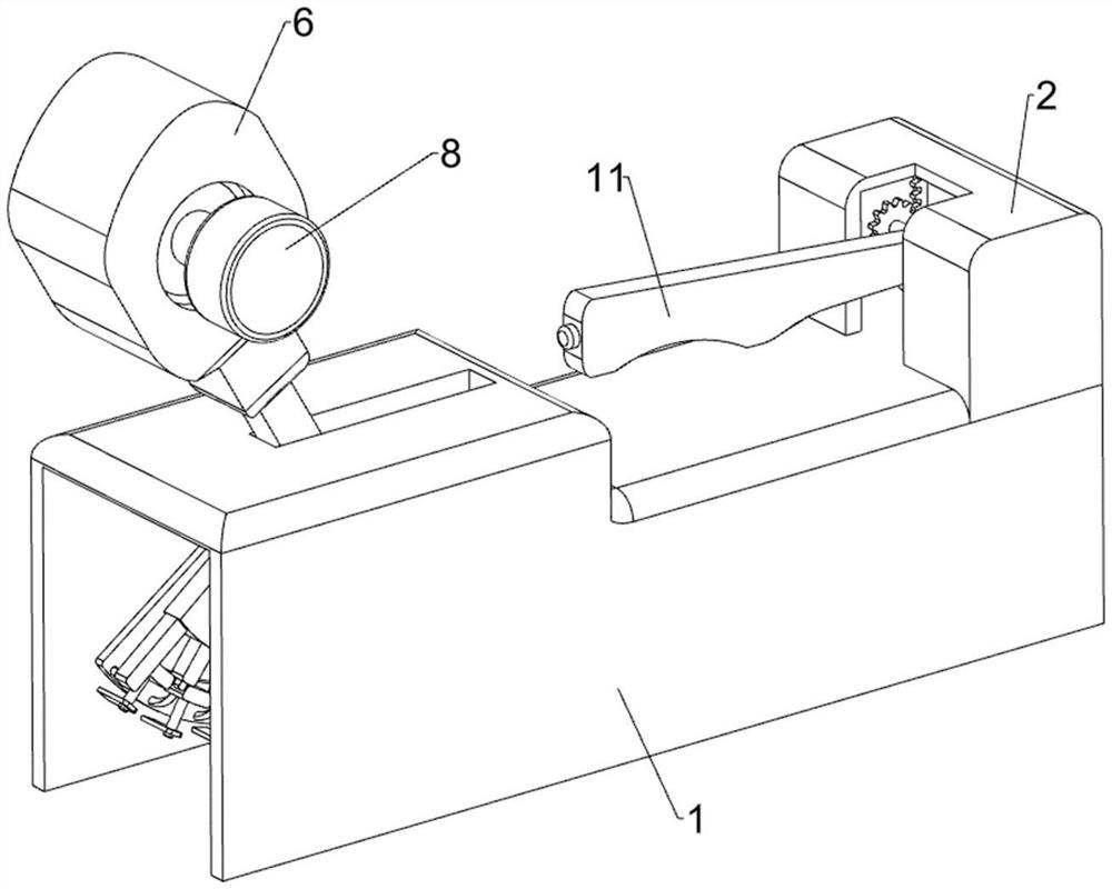
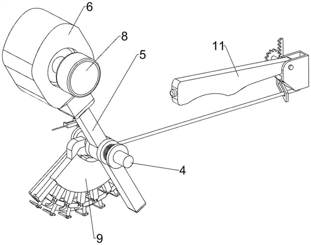
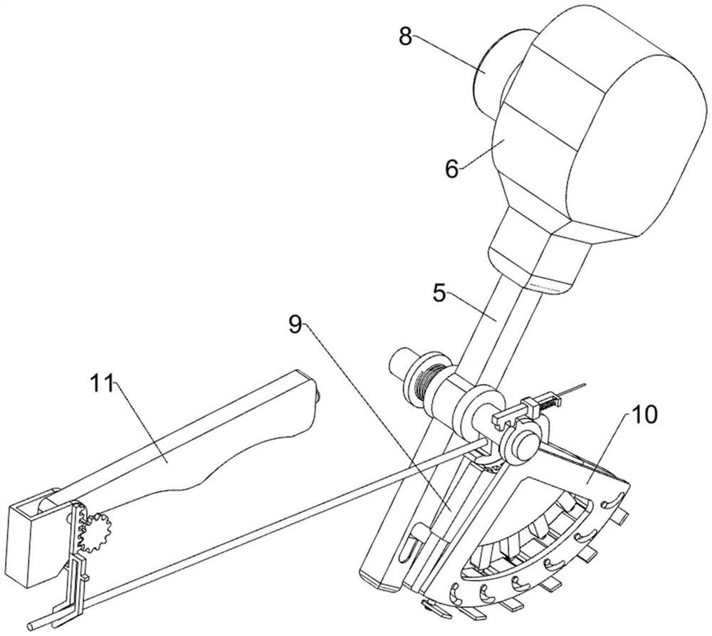
[0045] A new energy vehicle shift lock and parking assistance mechanism, such as figure 1 , figure 2 , image 3 , Figure 4 , Figure 5 , Image 6 , Figure 7 , Figure 8 with Figure 9 As shown, it includes an outer frame 1, a protective frame 2, a first fixed shaft 3, a second fixed shaft 4, a rotating rod 5, a gear handle 6, a torsion spring 7, a first locking assembly 8, a shifting assembly 9 and a second Two locking components 10, the outer top right side of the outer frame 1 is connected with the protective frame 2 by welding, the inner rear side of the outer frame 1 is fixedly connected with the first fixed shaft 3, and the inner front side of the outer frame 1 is fixedly connected with the second fixed shaft The shaft 4, the first fixed shaft 3 and the second fixed shaft 4 are jointly rotatably connected with a rotating rod 5, and the rotating rod 5 is slidably matched with the outer frame 1, and the upper part of the rotating rod 5 is fixedly connected with a ge...
Embodiment 2
[0051] On the basis of Example 1, such as Figure 10 , Figure 11 with Figure 12 As shown, it also includes a parking back gear assembly 11. The parking back gear assembly 11 is arranged on the first fixed shaft 3. The parking back gear assembly 11 is used to reset the shift lever 94 to the P position when the power is cut off. The parking backstop assembly 11 includes an arc-shaped magnetic block 111, a second fixed rod 112, a first coil spring 113, a circular magnetic block 114, a third fixed rod 115, a fixed frame 116, a rotating shaft 117, a hand brake lever 118, Flat gear 119, sliding guide frame 1111 and second tooth bar 1112, first fixed shaft 3 bottoms are slidably connected with arc-shaped magnetic block 111, and arc-shaped magnetic block 111 has magnetism, and the upper part of sliding bar 93 is fixedly connected with second fixed Rod 112, the second fixed rod 112 is located inside the first fan-shaped plate 92, the first coil spring 113 is connected between the s...
Embodiment 3
[0054] On the basis of Example 2, such as Figure 13 As shown, a labor-saving assembly 12 is also included, and the labor-saving assembly 12 is arranged on the first slider 81. The labor-saving assembly 12 is used to reduce the force of the driver when pressing the locking block 82. The labor-saving assembly 12 includes a fixed block 121 and a roller 122. A pair of fixed blocks 121 are connected to the side of the first slider 81 away from the locking block 82 by welding. The fixed blocks 121 are rotatably connected with rollers 122 , and the rollers 122 cooperate with the wedge block 84 in a rolling manner.
[0055] When the locking block 82 is pressed, the roller 122 rolls on the wedge-shaped block 84, so that the locking block 82 can be pressed more easily, which saves effort.
PUM
 Abstract
Description
Claims
Application Information
 - R&D
- Intellectual Property
- Life Sciences
- Materials
- Tech Scout
- Unparalleled Data Quality
- Higher Quality Content
- 60% Fewer Hallucinations
Browse by: Latest US Patents, China's latest patents, Technical Efficacy Thesaurus, Application Domain, Technology Topic, Popular Technical Reports.
© 2025 PatSnap. All rights reserved.Legal|Privacy policy|Modern Slavery Act Transparency Statement|Sitemap|About US| Contact US: help@patsnap.com


