Double-shifting-fork gear shifting structure, gearbox and vehicle

A technology of shift fork shaft and shift fork, applied in the field of gearbox, can solve the problems of unfriendly ergonomics, out-of-gear, shift fork wear, etc.

Pending Publication Date: 2022-03-29
LOVOL HEAVY IND CO LTD
View PDF0 Cites 0 Cited by
  • Summary
  • Abstract
  • Description
  • Claims
  • Application Information

AI Technical Summary

Problems solved by technology

[0002] At present, the gear positions of crawler gearboxes are mostly three-speed structures, and the gears are mostly shifted by double-connected shift forks, that is, the double-connected shift forks with springs and steel balls are used to move on the shift fork shaft with annular grooves. The shifting gear is realized by the dynamic meshing sleeve. With the increase of the mass of the machine, the horsepower of the engine and the feeding amount, this structure gradually shows many disadvantages, such as the wear and tear of the shift fork and the problem of gear disengagement. By increasing the spring force, the gear disengagement can be prevented. The problem is that the handling force is too large, and the ergonomics are not friendly

Method used


Image

  • Double-shifting-fork gear shifting structure, gearbox and vehicle
  • Double-shifting-fork gear shifting structure, gearbox and vehicle
  • Double-shifting-fork gear shifting structure, gearbox and vehicle

Examples


Embodiment 1

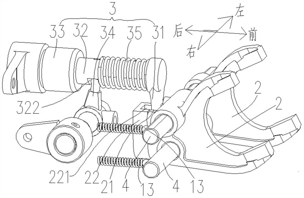
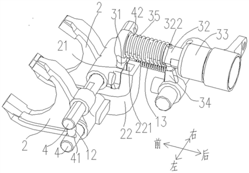
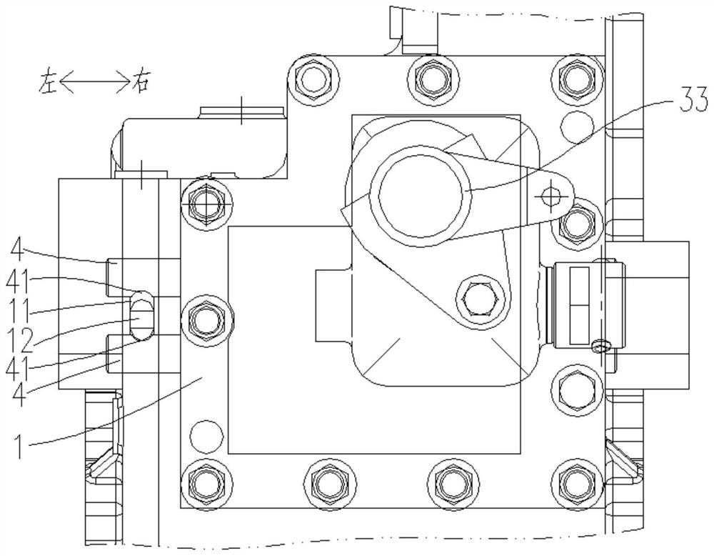
[0035] Such as Figure 1-Figure 7 As shown, this embodiment provides a double-fork shift structure, including a housing 1, two shift forks 2, a drive assembly 3 and two fork shafts 4 installed on the housing 1 ;

[0036] The two shift forks 2 are arranged vertically, and are distributed at intervals along the left and right directions, and the fork openings of the two shift forks 2 are all facing forward;

[0037] The two shift fork shafts 4 are arranged horizontally along the left and right directions and are slidably connected with the housing 1, and are distributed at intervals along the up and down directions, and the two shift fork shafts 4 are connected to the two shift forks 2 one by one. Correspondingly, each said shift fork shaft 4 is connected and fixed with the corresponding said shift fork 2, and is slidably connected with another said shift fork 2, and any one of said shift fork shafts 4 can be relative to said shift fork. The housing 1 slides left and right and...

Embodiment 2

[0049] This embodiment provides a gearbox, including the double shift fork shift structure as described in Embodiment 1 (the two shift forks of the double shift fork shift structure act on the two shift forks on the same transmission shaft on the gearbox. a clutch sleeve).

Embodiment 3

[0051] This embodiment provides a kind of vehicle, comprises gearbox as described in embodiment 2, and this vehicle can be engineering vehicle also can be agricultural vehicle (especially suitable for crawler type engineering vehicle or crawler type agricultural vehicle, as crawler excavator , crawler bulldozers, crawler harvesters, etc.).


PUM


Abstract

The invention discloses a double-shifting-fork gear shifting structure, a gearbox and a vehicle. The double-shifting-fork gear shifting structure comprises a shell, two gear shifting forks, a driving assembly and two shifting fork shafts, wherein the driving assembly and the shifting fork shafts are installed on the shell. The two gear shifting forks are vertically arranged and distributed in the left-right direction in a spaced mode, and shifting fork acting fork openings of the two gear shifting forks face forwards. The two shifting fork shafts are horizontally arranged in the left-right direction, slidably connected with the shell and distributed in the up-down direction at intervals, the two shifting fork shafts correspond to the two gear shifting forks one to one, and each shifting fork shaft is fixedly connected with the corresponding gear shifting fork and slidably connected with the other gear shifting fork. Any shifting fork shaft can slide left and right relative to the shell and drive the corresponding gear shifting fork to slide left and right. The driving assembly is installed on the shell and used for selectively driving any gear shifting fork to move left and right relative to the other gear shifting fork so as to engage a gear or move to a reset position so as to engage a neutral gear, and the structure is simple.

Description

technical field [0001] The invention belongs to the field of gearboxes, and in particular relates to a double shift fork shift structure, a gearbox and a vehicle. Background technique [0002] At present, the gear positions of crawler gearboxes are mostly three-speed structures, and the gears are mostly shifted by double-connected shift forks, that is, the double-connected shift forks with springs and steel balls are used to move on the shift fork shaft with annular grooves. The shifting gear is realized by the dynamic meshing sleeve. With the increase of the mass of the machine, the horsepower of the engine and the feeding amount, this structure gradually shows many disadvantages, such as the wear and tear of the shift fork and the problem of gear disengagement. By increasing the spring force, the gear disengagement can be prevented. The problem is that the handling force is too large and the ergonomics are not friendly. Contents of the invention [0003] In order to sol...

Claims


Application Information

Patent Timeline
IPC IPC(8): F16H63/32F16H63/34F16H63/30
CPCF16H63/32F16H63/3408F16H2063/3089F16H2063/325
Inventor 亓文正董云蓬马滨刘汉斌冯向梁赵文科王志全
Owner LOVOL HEAVY IND CO LTD
Why Eureka
Try Eureka