Throttling device

A throttling device and throttling control technology, which can be used in fluid circulation arrangements, mechanical equipment, refrigeration safety arrangements, etc., and can solve the problems of refrigerant retention, increased liquid supply, and increased flow capacity of the orifice of the throttling orifice. , to achieve the effect of reducing unit cost, improving performance and stability

Active Publication Date: 2018-09-07
YORK WUXI AIR CONDITIONING & REFRIGERATION CO LTD +1
View PDF8 Cites 0 Cited by
  • Summary
  • Abstract
  • Description
  • Claims
  • Application Information

AI Technical Summary

Problems solved by technology

When the air conditioning system is in the heating state, because the system pressure difference in the heating state is larger than that in the cooling state, the flow capacity of the orifice of the throttle orifice becomes larger, and the liquid supply becomes larger, causing the refrigerant to stay in the In the evaporator 110, the condenser 130 is short of liquid, and finally the subcooling degree of the condenser 130 is very small, so that the heating performance of the system is very poor
In addition, because the refrigerant stays in the evaporator 110, it may also cause safety problems such as suction of the compressor 120 with liquid.
In other words, the throttling device in the prior art can only guarantee the application performance in the cooling state, but cannot guarantee its application performance in the heating state

Method used


Image

  • Throttling device
  • Throttling device
  • Throttling device

Examples


Embodiment Construction

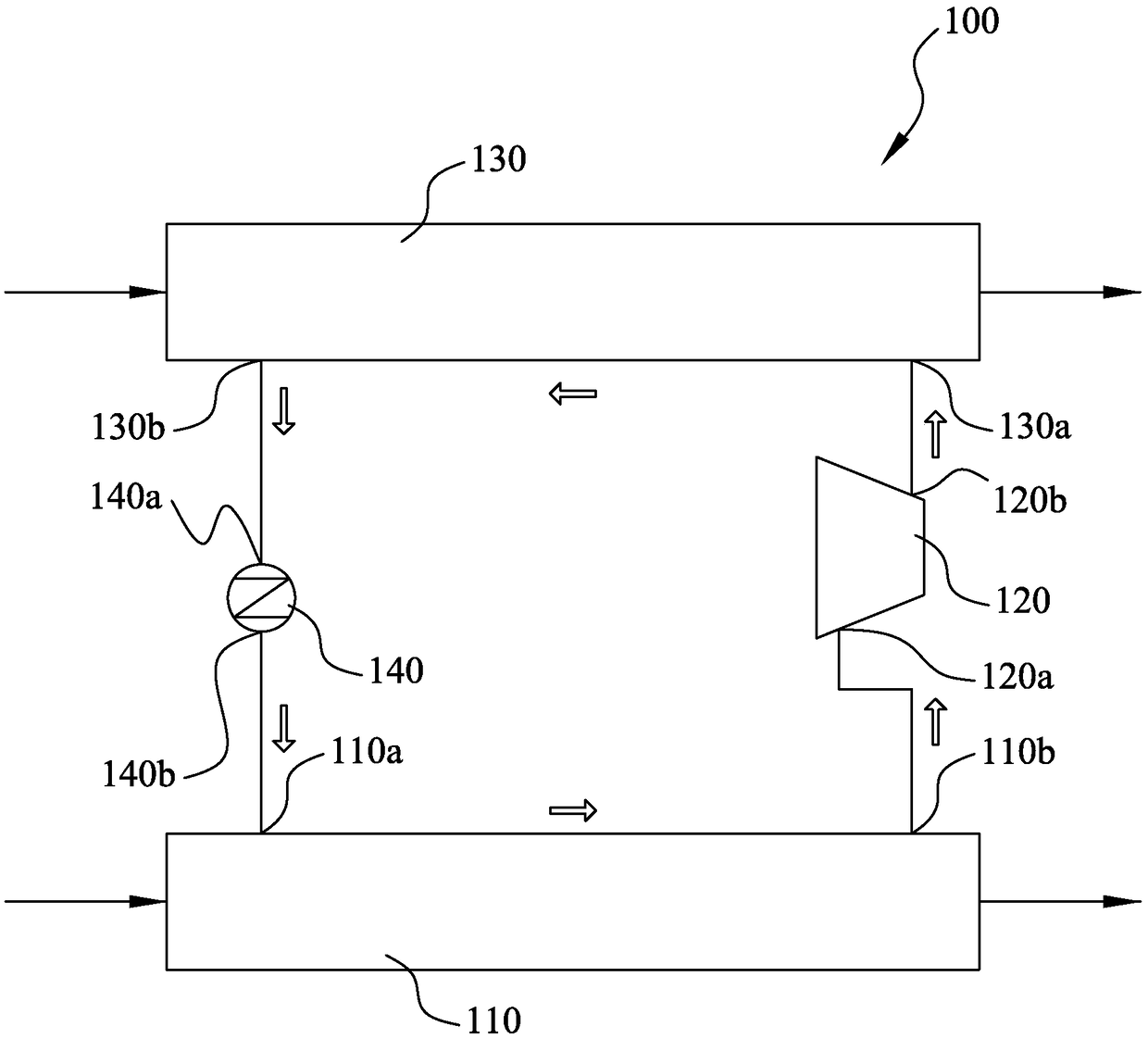
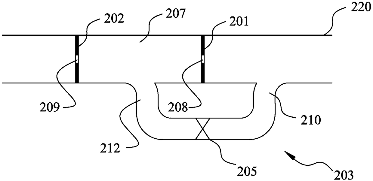
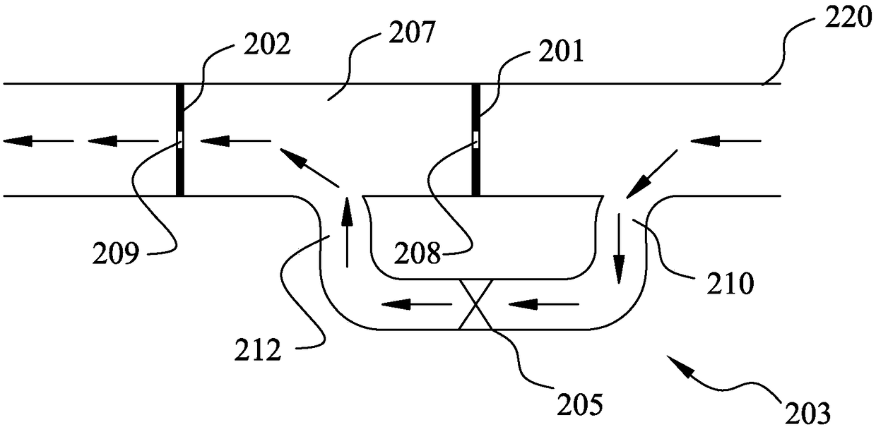
[0042] Various embodiments of the invention will be described below with reference to the accompanying drawings, which form a part hereof. It should be understood that although terms indicating direction are used in the present invention, such as "front", "rear", "upper", "lower", "left", "right", etc. to describe the direction or orientation of the present invention Various example structural parts and elements, but these terms are used herein for explanatory purposes only, based on the example orientations shown in the drawings. Since the disclosed embodiments of the present invention may be arranged in different orientations, these directional terms are for illustration only and should not be viewed as limiting. In the following drawings, the same reference numerals are used for the same components, and the similar reference numerals are used for similar components to avoid repeated descriptions.

[0043] Figure 2A A throttling device according to an embodiment of the in...


PUM


Abstract

The invention provides a throttling device. The throttling device is used for controlling a pressure difference of a refrigerant between an inlet and an outlet of a liquid supply pipe inside an air conditioning system, wherein the throttling device is arranged inside the liquid supply pipe; the throttling device comprises a first throttling control device, a second throttling control device and abypass channel capable of being controllably connected or disconnected; the first throttling control device is arranged on the upstream of the liquid supply pipe, the second throttling control deviceis arranged downstream of the first throttling control device, one end of the bypass channel is connected to the upstream of the first throttling control device, and the other end of the bypass channel is connected to a connecting channel between the first throttling control device and the second throttling control device; and the first throttling control device and the second throttling control device are correspondingly provided with a channel to allow a fluid to pass through the channels, so that the pressure difference of the fluid flowing through the channels is changed, and the pressuredifference between the two ends of the liquid supply pipe is controlled. The bypass channel is connected or disconnected according to the running state of the air conditioning system, so that the application performance of the air conditioning system can be improved, and the safety operation of the air conditioning system can be protected.

Description

technical field [0001] The invention relates to a throttling device, in particular to a throttling device used in an air-conditioning system. Background technique [0002] A traditional air conditioning system consists of four major components: a compressor, a condenser, a throttling device, and an evaporator, which are used to circulate the refrigerant in it, thereby completing the refrigeration cycle or heating cycle through the state change of the refrigerant. [0003] specifically, figure 1 A schematic structural diagram of a conventional air conditioning system 100 is shown. The air conditioning system 100 mainly includes an evaporator 110, a compressor 120, a condenser 130 and a throttling device 140, which are connected through pipelines to form a closed system, and the system is filled with refrigerant. like figure 1 As shown, the evaporator 110 includes an inlet 110a and an outlet 110b, the compressor 120 includes an inlet 120a and an outlet 120b, the condenser 1...

Claims


Application Information

Patent Timeline
Patent Type & Authority Applications(China)
IPC IPC(8): F25B41/06F25B49/02F25B41/31
CPCF25B49/02F25B41/30
Inventor 季士才
Owner YORK WUXI AIR CONDITIONING & REFRIGERATION CO LTD
Why Eureka
Try Eureka