Luminous key structure

A key and layer structure technology, applied in the direction of electrical components, electrical switches, circuits, etc., can solve the problems of effective shading of light guide plates, light leakage of keycaps, restrictions, etc., and achieve the effect of small height

Active Publication Date: 2018-09-07
DARFON ELECTRONICS (SUZHOU) CO LTD +1
View PDF8 Cites 3 Cited by
  • Summary
  • Abstract
  • Description
  • Claims
  • Application Information

AI Technical Summary

Problems solved by technology

Considering the optical effect, the design of the light guide plate and the shielding sheet will keep the structure intact, but this will limit the reduction of the height of the light-emitting button structure
And if the structure of the light guide plate and the shielding sheet is designed to form an avoidance space to avoid structural interference between the structure and the light guide plate and the shielding sheet when the light-emitting button structure is actuated, the shielding sheet may fail to effectively shield the light guide plate, making the Users may observe light leakage around the keycap from above the illuminated key structure
Therefore, the current light-emitting button structure has the aforementioned difficulties in thinning

Method used


Image

  • Luminous key structure
  • Luminous key structure
  • Luminous key structure

Examples


Embodiment Construction

[0031] In order to have a further understanding of the purpose, structure, features, and functions of the present invention, the following detailed descriptions are provided in conjunction with the embodiments.

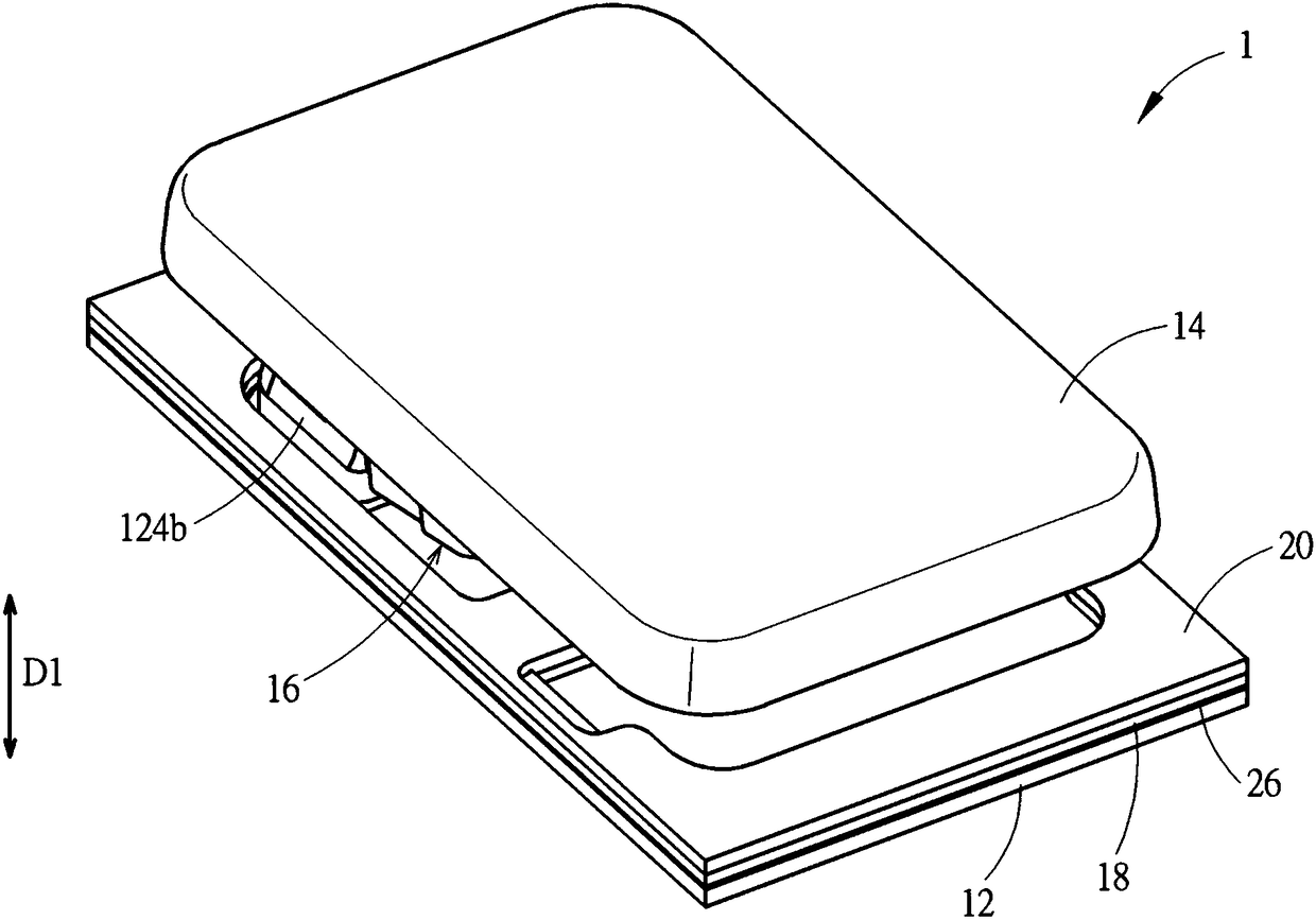
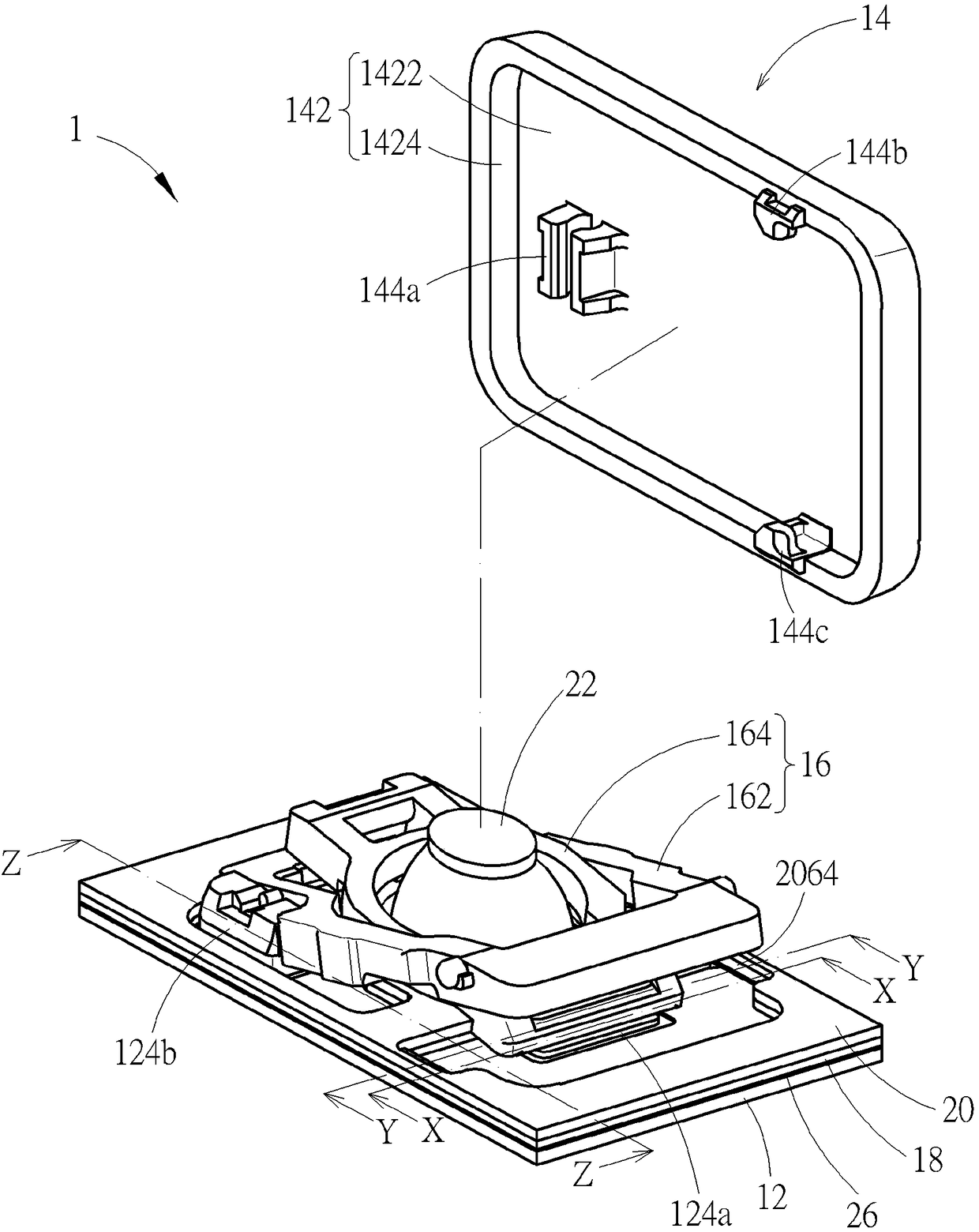
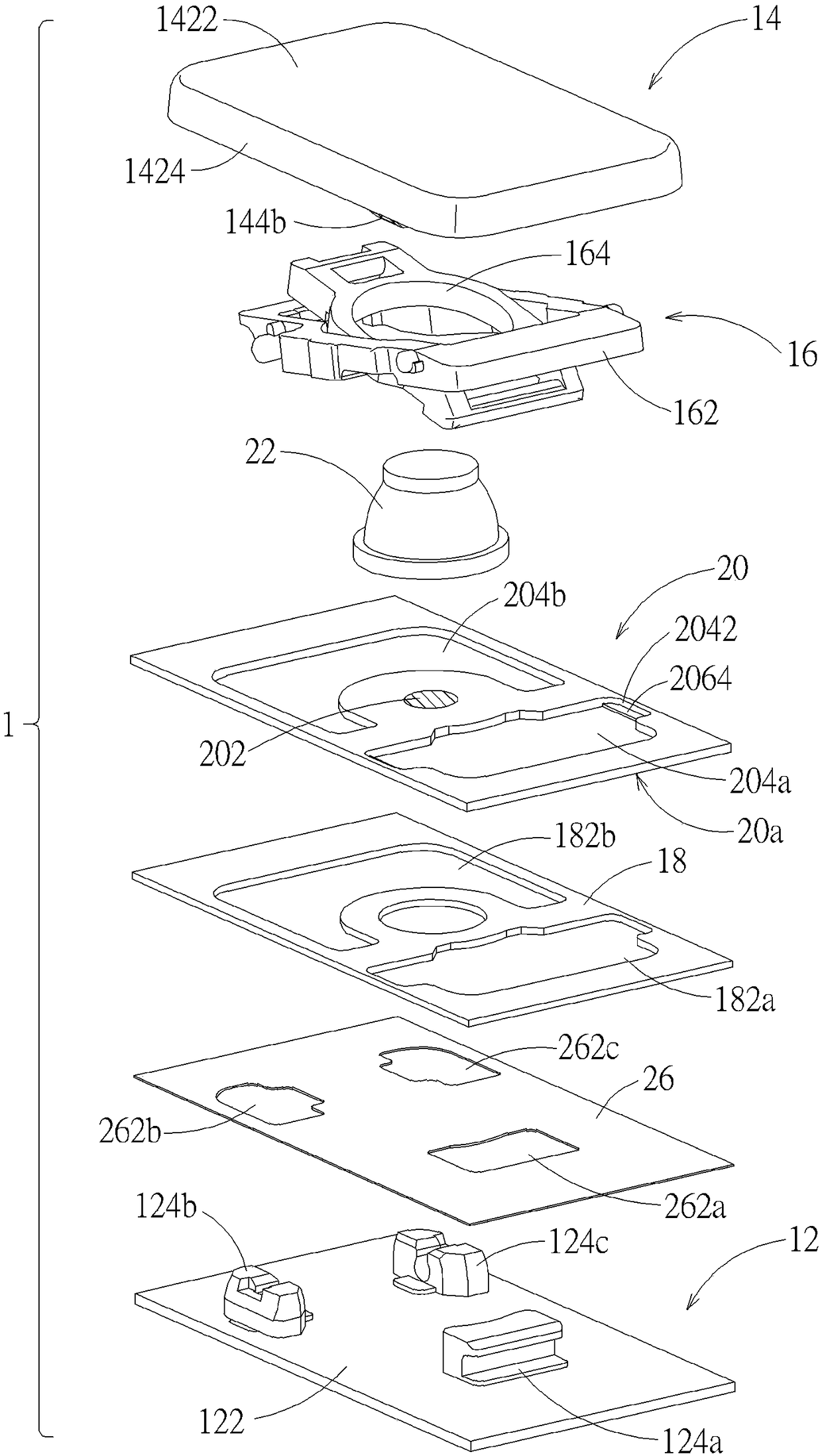
[0032] see Figure 1 to Figure 4 . figure 1 It is a schematic diagram of the light-emitting button structure of the embodiment of the present invention; figure 2 for figure 1 The schematic diagram of partial explosion of the luminous key structure; image 3 for figure 1 Exploded diagram of the illuminated button structure; Figure 4 for image 3 The bottom view of the layered circuit board with the light-emitting key structure to show the coating range of the light-shielding coating layer thereon. The light-emitting key structure 1 of the embodiment of the present invention includes a base 12, a keycap 14, a lifting mechanism 16, a light guide plate 18, a layered circuit board 20 (to simplify the diagram, it is still shown as a single structural part in princip...


PUM


Abstract

The present invention discloses a luminous key structure. The structure comprises a base, a key cap, a ascending and descending mechanism connecting between the base and the key cap, a light-guiding plate located on the base, a layered circuit board located on the light-guiding plate and a light-shading coating layer. The light-guiding plate is provided with groove(s) located under the key cap. The layered circuit board comprises multiple overlapped structure layers, and the layered circuit board has a first opening hole, wherein the first opening hole is located under the key cap, and the first opening hole is connected with the corresponding groove. A bottom structure layer in the multiple structure layers is provided with bulge part(s), wherein each bulge part extends from a side wall face to the inner side of the key cap, the first opening hole is provided with the side wall face, and the side wall face turns towards the inner side of the key cap. The light-shading coating layer iscoated on the surface, turning towards the base, of the bulge part. When the key cap is pressed, a first connection structure of the key cap enters into the corresponding first opening hole and the corresponding groove to allow the corresponding bulge part to deform elastically, so that the corresponding bulge part enters into the corresponding groove. The luminous key structure has lower height,and the luminous key structure can maintain a considerable degree of light-shading effect.

Description

technical field [0001] The invention relates to a button structure, in particular to a light-emitting button structure. Background technique [0002] Compared with the general button structure, the light-emitting button structure needs to include a light guide plate and a shielding sheet on it. Considering the optical effect, the design of the light guide plate and the shielding sheet will keep the structure intact, but this will limit the reduction of the height of the light-emitting button structure. And if the structure of the light guide plate and the shielding sheet is designed to form an avoidance space to avoid structural interference between the structure and the light guide plate and the shielding sheet when the light-emitting button structure is actuated, the shielding sheet may fail to effectively shield the light guide plate, making the Users may observe light leakage around the keycaps from above the illuminated key structure. Therefore, the current light-emit...

Claims


Application Information

Patent Timeline
Patent Type & Authority Applications(China)
IPC IPC(8): H01H13/02
Inventor 蔡柏伟彭勋昆
Owner DARFON ELECTRONICS (SUZHOU) CO LTD
Why Eureka
Try Eureka