
A compact multi-band antenna

A multi-band antenna and compact technology, applied in the field of communication, can solve the problems of unfavorable integration and large antenna size, and achieve the effect of small size, wide application and good matching

Active Publication Date: 2020-04-03
HARBIN ENG UNIV
View PDF2 Cites 0 Cited by
  • Summary
  • Abstract
  • Description
  • Claims
  • Application Information

AI Technical Summary

Problems solved by technology

However, the size of the antenna is large, which is not conducive to integration

Method used


Image

  • A compact multi-band antenna
  • A compact multi-band antenna
  • A compact multi-band antenna

Examples


specific Embodiment 1

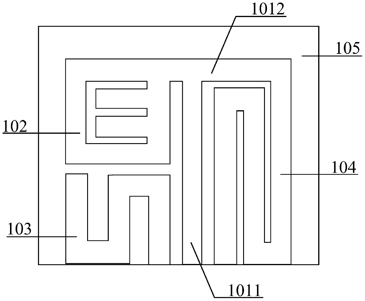
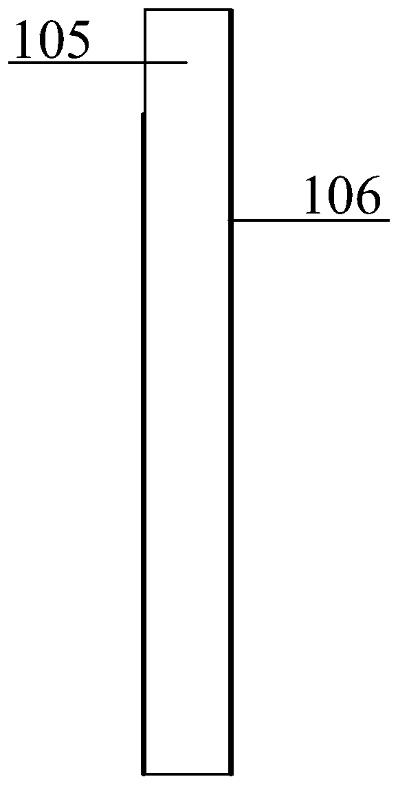
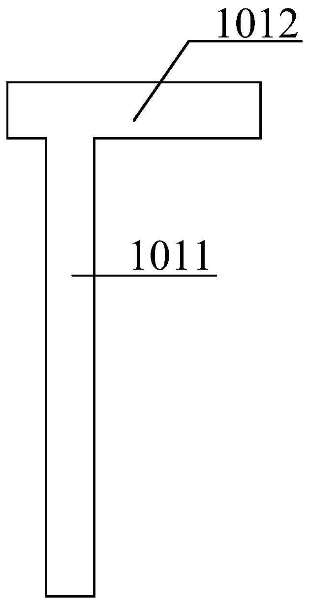
[0020] The antenna involved in the present invention mainly includes a dielectric substrate 105, a T-shaped microstrip transmission line arranged on the dielectric substrate, a first rectangular radiating unit 102 (only one embodiment of the present invention), and a second S-shaped radiating unit 103 (only An embodiment of the present invention), the third S-shaped radiating unit 104, and the ground plane 106 arranged under the dielectric substrate, the first rectangular radiating unit 102 and the third S-shaped radiating unit 104 are connected by a T-shaped microstrip transmission line, The T-shaped microstrip transmission line is composed of a vertical microstrip line 1011 and a horizontal microstrip line 1012. The first rectangular radiating unit 102 and the third S-shaped radiating unit 104 are fed in a parallel feeding manner. The second S-shaped radiating unit 103 is fed in a coupling feeding manner. By adjusting the size of each radiation unit, the size of the E-shaped...

specific Embodiment 2

[0026] The purpose of the present invention is achieved as follows: including a dielectric substrate 105, a T-shaped microstrip transmission line arranged on the dielectric substrate, a first rectangular radiating unit 102, a second S-shaped radiating unit 103, a third S-shaped radiating unit 104, and The ground plane 106 is arranged under the dielectric substrate, the first rectangular radiating unit 102 is etched with an E-shaped groove, the first rectangular radiating unit 102 and the third S-shaped radiating unit 104 are connected by a T-shaped transmission line, and the lower end of the T-shaped transmission line is connected to The inner conductor of the connector is connected, and the outer conductor of the connector is connected to the ground plane.

[0027] The present invention also includes such structural features:

[0028] 1. The antenna adopts a hybrid feeding method, the first rectangular radiating unit 102 and the second S-shaped radiating unit 103 adopt a serial fe...


PUM


Abstract

The invention belongs to the communication field, and specifically relates to a compact multiband antenna comprising a medium substrate 105, a T-type microstrip transmission line arranged on the medium substrate, a first rectangular radiation unit 102, a second S-type radiation unit 103, a third S-type radiation unit 104, and a ground surface 106 arranged below the medium substrate; the first rectangular radiation unit 102 is etched with an E-shaped groove, and connected with the third S-type radiation unit 104 via the T-type transmission line; the bottom of the T-type transmission line is connected with an inner conductor of a connector; an outer conductor of the connector is connected with the ground surface 106. The compact multiband antenna employs the T-type microstrip transmission line to feed, radiation units are directly and indirectly combined to feed, and the multi radiation units are fused to realize the antenna multiband design, thus obtaining low profile and miniaturization design effects.

Description

Technical field [0001] The invention belongs to the field of information and communication, and specifically relates to a compact multi-band antenna. Background technique [0002] Since the beginning of the 20th century, with the rapid development of information technology, electronic communication, and multimedia technology, people have increasingly demanded high-speed, large-capacity, and high-performance mobile communication systems. The communication transmission rate of mobile terminal equipment is gradually increasing, and communication protocol standards are increasing. Therefore, the antenna in the terminal equipment is required to cover different working protocol standards and working frequency bands. However, due to the relatively small volume of mobile terminal equipment, the design of multiple transceiver antennas is obviously restricted by space and is prone to coupling effects, which seriously affects the communication quality. On the other hand, the rapid developm...

Claims


Application Information

Patent Timeline
Patent Type & Authority Patents(China)
IPC IPC(8): H01Q1/38H01Q1/48H01Q1/50H01Q5/10
CPCH01Q1/38H01Q1/48H01Q1/50H01Q5/10
Inventor 李迎松董玥
Owner HARBIN ENG UNIV
Learn More