Miniaturization multi-resonance antenna

A multi-resonance and antenna technology, applied in the field of antenna structure, can solve problems such as difficult independent design, inflexible design, and difficult adjustment, and achieve the effect of easy flexible design, low cost, and good matching

Active Publication Date: 2018-02-09
HARBIN ENG UNIV
View PDF8 Cites 2 Cited by
  • Summary
  • Abstract
  • Description
  • Claims
  • Application Information

AI Technical Summary

Problems solved by technology

However, the frequency bands of this antenna are mutually restricted, it is difficult to achieve independent design, it is not easy to adjust in actual engineering, and the size of the antenna is relatively large
In addition, Andrea Michel et al. d

Method used


Image

  • Miniaturization multi-resonance antenna
  • Miniaturization multi-resonance antenna
  • Miniaturization multi-resonance antenna

Examples


Embodiment Construction

[0015] The present invention will be further described in detail below in conjunction with the accompanying drawings and specific embodiments.

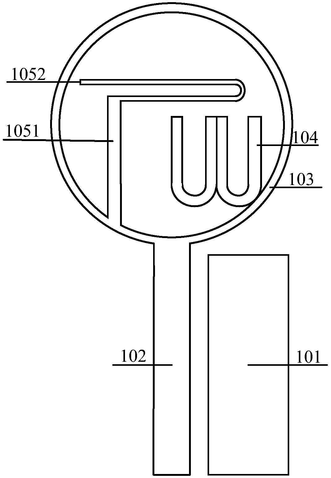
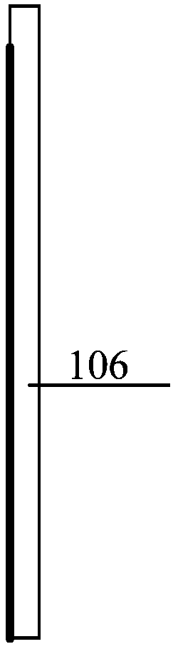
[0016] combine Figure 1 to Figure 4 , the antenna of the present invention mainly includes a dielectric substrate 106, an asymmetric coplanar line feeding transmission line 102, a ground plane 101, a ring radiating unit 103, a double U-shaped radiating unit 104 and a monopole radiating unit. Both the double U-shaped radiating unit 104 and the monopole radiating unit are connected to the annular radiating unit, and are indirectly fed through the annular radiating unit, and the monopole radiating unit is composed of a vertical radiating unit 1051 and a bent radiating unit 1052 (only this an embodiment of the invention). By adjusting the size of each radiating element, the coupling between the monopole radiating element and the double U-shaped radiating element, and the coupling gap between the annular radiating element and the ground ...


PUM


Abstract

The invention provides a miniaturization multi-resonance antenna. The miniaturization multi-resonance antenna comprises a dielectric substrate, an annular radiation unit and a non-symmetric coplanar line feed transmission line arranged on the dielectric substrate, a parting structure radiation unit and a monopole radiation unit embedded in the annular radiation unit, and a half edge grounding plane arranged on the dielectric substrate; a dual-U-shaped radiation unit and the monopole radiation unit are both connected with the annular radiation unit; the non-symmetric coplanar line feed transmission line is connected with an inner conductor of an SMA; and an outer conductor of the SMA is connected with the grounding plane. The miniaturization multi-resonance antenna disclosed in the invention adopts the non-symmetric coplanar line feed structure and the inter-radiation-unit feed and multi-radiation-unit fusion design, so that a miniaturization design effect is achieved; and in addition,each radiation unit can be designed independently, so that multi-frequency-band design can be realized conveniently.

Description

technical field [0001] The invention relates to an antenna structure, in particular to a miniaturized multi-resonance antenna. Background technique [0002] In recent years, the rapid development of wireless communication technology has been deeply rooted in the hearts of users, which has brought great convenience to our daily life. In an instant, the whole earth has become a global village, making people more and more dependent on wireless communication technology. getting stronger. From the transmission of text and voice to the current high-definition image transmission, the development of wireless communication is changing with each passing day, and the requirements for transmission rate and transmission bandwidth are also getting higher and higher. Especially in recent years, the rapid development of WiFi technology seems to make people unable to leave the high-speed transmission of WiFi. In order to meet the needs of users, WiFi usually works in two frequency bands. A...

Claims


Application Information

Patent Timeline
IPC IPC(8): H01Q1/36H01Q1/50H01Q5/10
CPCH01Q1/36H01Q1/50H01Q5/10
Inventor 李迎松石万录焦天奇
Owner HARBIN ENG UNIV
Why Eureka
Try Eureka