Ring winding dual-rotor permanent-magnet synchronous motor with electromagnetic linkage device

A linkage device and ring winding technology, applied in the direction of electromechanical devices, electric components, magnetic circuit rotating parts, etc., can solve the problems of poor magnetic density matching between internal and external air gaps, low output torque, and difficulty in meeting high-efficiency operation of motors

Pending Publication Date: 2018-09-07
HARBIN UNIV OF SCI & TECH
View PDF0 Cites 6 Cited by
  • Summary
  • Abstract
  • Description
  • Claims
  • Application Information

AI Technical Summary

Problems solved by technology

The motor has no stator structure, the original motor stator is used as the outer rotor, and the inner rotor adopts a permanent magnet structure. Using the principle of action force and reaction force, the inner and outer rotors move in opposite directions, and the inner and outer rotors rotate in the same direction through the universal joint device; application Universal joints and deceleration devices used in hybrid electric vehicles not only increase the space occupied, but also cannot make full use of the output torque; the permanent magnets of the inner and outer rotors are surface-mounted, with low salient pole ratio and poor speed regulation performance. The continuous battery life is low, and it is difficult

Method used


Image

  • Ring winding dual-rotor permanent-magnet synchronous motor with electromagnetic linkage device
  • Ring winding dual-rotor permanent-magnet synchronous motor with electromagnetic linkage device
  • Ring winding dual-rotor permanent-magnet synchronous motor with electromagnetic linkage device

Examples


Embodiment

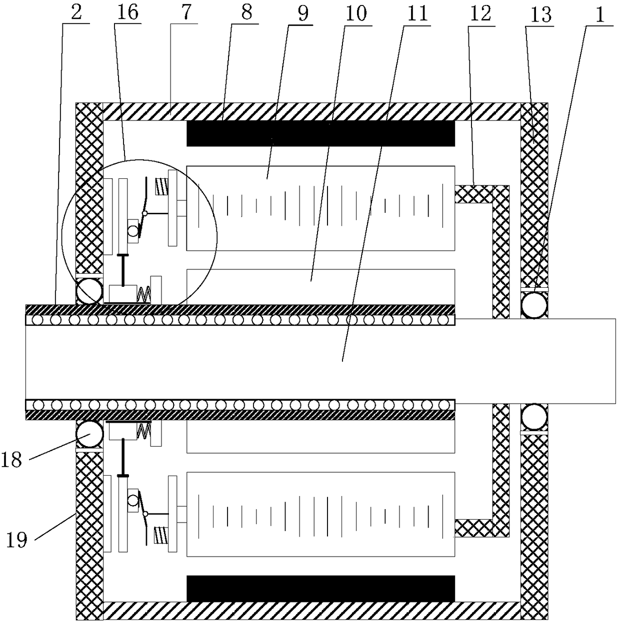
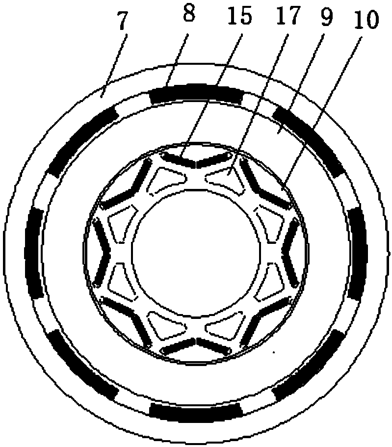
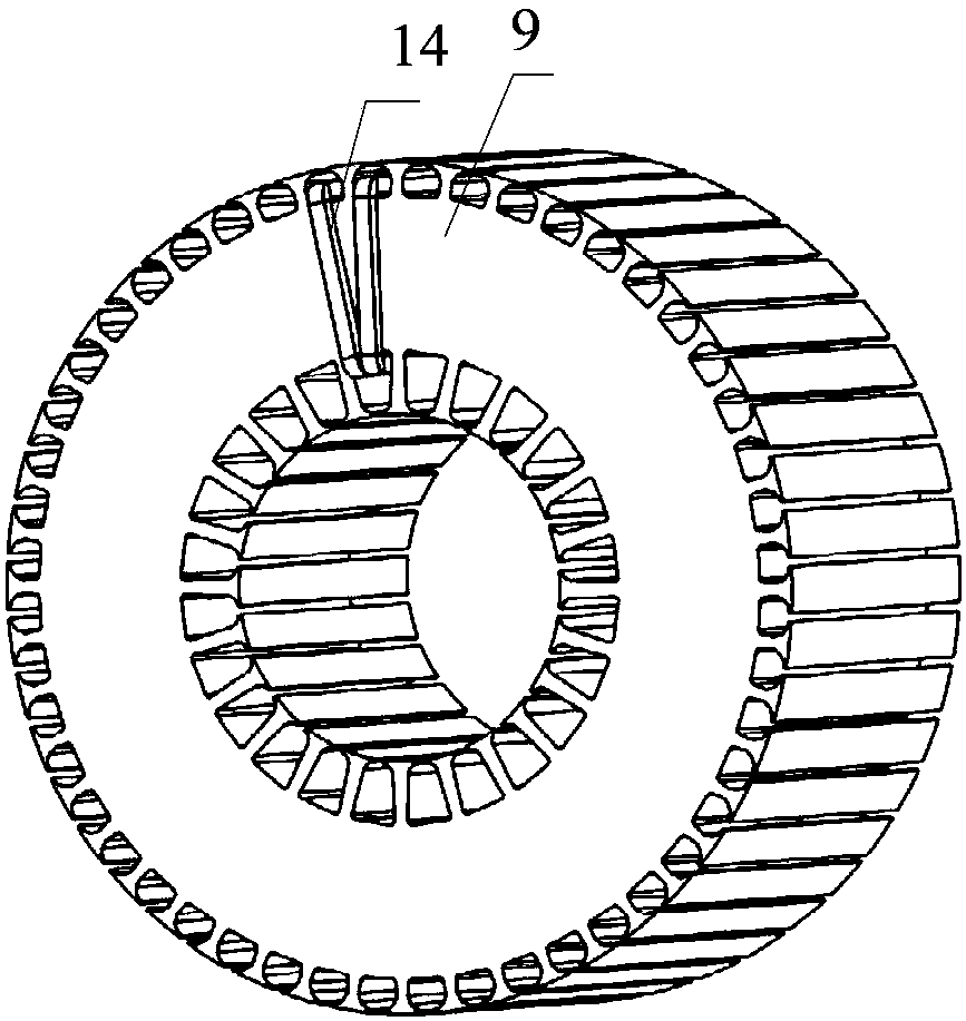
[0024] Example: see Figure 1-Figure 5 , a ring-winding double-rotor permanent magnet synchronous motor with an electromagnetic linkage device in this embodiment, comprising a shaft sleeve 2, an inner rotor 10, a motor shaft 11, an outer rotor 7, a stator 9 and a fixed bracket 12, the inner rotor 10 and the outer rotor 7 are both permanent magnet structures, the stator 9 adopts annular winding, the shaft sleeve 2 is rotatably fitted on the motor shaft 11, the right end of the motor shaft 11 passes through the shaft sleeve 2, and the inner rotor 10 is fixedly sleeved on the shaft sleeve On the cylinder 2, the stator 9 is set on the outside of the inner rotor 10, leaving a gap between the two. The stator 9 is fixedly connected to the motor shaft 11 through the fixed bracket 12. The outer rotor 7 is set on the outside of the stator 9, leaving a gap between the two. The left end of the outer rotor 7 The first flange 19 and the first bearing 18 are connected to the shaft sleeve 2, ...


PUM


Abstract

The invention discloses a ring winding dual-rotor permanent-magnet synchronous motor with an electromagnetic linkage device, and belongs to the technical field of the motor. The technical problems solved by the invention are as follows: the motor operation efficiency is low, the internal-external gap flux density matching is bad, the output torque is low, and the speed control performance is bad.An internal rotor and an external rotor are permanent-magnet structure, a stator adopts the ring winding, a shaft sleeve is rotatably sleeved on a motor shaft, the right end of the motor shaft piercesthe shaft sleeve, the internal rotor is fixedly sleeved on the shaft sleeve, the stator is sleeved on the external of the internal rotor, and the gap is formed between the stator and the intern rotor; the stator is fixedly connected with the motor shaft through a fixed bracket, the external rotor is sleeved on the external of the stator, and the gap is formed between the external rotor and the stator; the left end of the external rotor is connected with the shaft sleeve through a first flange plate and a first bearing, and the right end of the external rotor is connected with the motor shaftthrough a second flange plate and a second bearing; the permanent magnet synchronous motor further comprises an electromagnetic linkage device, and the internal rotor and the external rotor realize the synthetic rotation through the electromagnetic linkage device. The ring winding dual-rotor permanent-magnet synchronous motor disclosed by the invention can be applied to a hybrid power vehicle driving system.

Description

technical field [0001] The invention relates to a permanent magnet synchronous motor, in particular to a circular winding double-rotor permanent magnet synchronous motor with an electromagnetic linkage device, belonging to the technical field of motors. Background technique [0002] The existing double-rotor permanent magnet motor mostly adopts traditional stacked windings, which is a counter-rotating structure, and universal joints and speed reduction devices are required for vehicles. The motor has no stator structure, the original motor stator is used as the outer rotor, and the inner rotor adopts a permanent magnet structure. Using the principle of action force and reaction force, the inner and outer rotors move in opposite directions, and the inner and outer rotors rotate in the same direction through the universal joint device; application Universal joints and deceleration devices used in hybrid electric vehicles not only increase the space occupied, but also cannot ma...

Claims


Application Information

Patent Timeline
IPC IPC(8): H02K16/02H02K3/28H02K7/00H02K1/16H02K1/27H02K1/32
CPCH02K16/02H02K1/165H02K1/2706H02K1/2786H02K1/32H02K3/28H02K7/003
Inventor 徐永明贾国强艾萌萌李果赵弟远薛向峰
Owner HARBIN UNIV OF SCI & TECH
Why Eureka
Try Eureka