Dampproof electrical cabinet

A technology for electrical cabinets and cabinets, which is applied to electrical equipment shells/cabinets/drawers, electrical components, cabinets/boxes/drawer parts, etc. Reduce and other problems to achieve the effect of extending service life, preventing moisture damage, and improving safety

Active Publication Date: 2018-09-07
陆牌电气科技有限公司
View PDF7 Cites 5 Cited by
  • Summary
  • Abstract
  • Description
  • Claims
  • Application Information

AI Technical Summary

Problems solved by technology

[0002] There are two main dehumidification methods in the existing fully enclosed electrical cabinets: one is to use heating to dehumidify, that is, to use an electric heater to heat the air in the electrical cabinet, because the air temperature in the electrical cabinet increases and the saturated humidity increases, so the relative humidity However, since the electrical cabinet is closed, the moisture cannot be discharged, so the absolute humidity does not change, and the electrical cabinet actually becomes a high-temperature and high-humidity environment, which is not good for the operation of electrical components; the other is to use refrigeration and dehumidification, which will The evaporator is installed in the electrical cabinet, and when the refrigerant evaporates, it absorbs heat, reduces the temperature in the electrical cabinet, and reduces the saturated humidity, so that the moisture in the air in the electrical cabinet is condensed and precipitated, and the condensed water is discharged out of the cabinet through the condensation pipe In addition, however, when the outdoor temperature is low, especially in the northern winter, the condensed water will freeze, resulting in the failure of dehumidification

Method used


Image

  • Dampproof electrical cabinet
  • Dampproof electrical cabinet
  • Dampproof electrical cabinet

Examples


Embodiment Construction

[0034] The technical solution of the present invention will be further described in detail below in conjunction with the accompanying drawings, but the protection scope of the present invention is not limited to the following description.

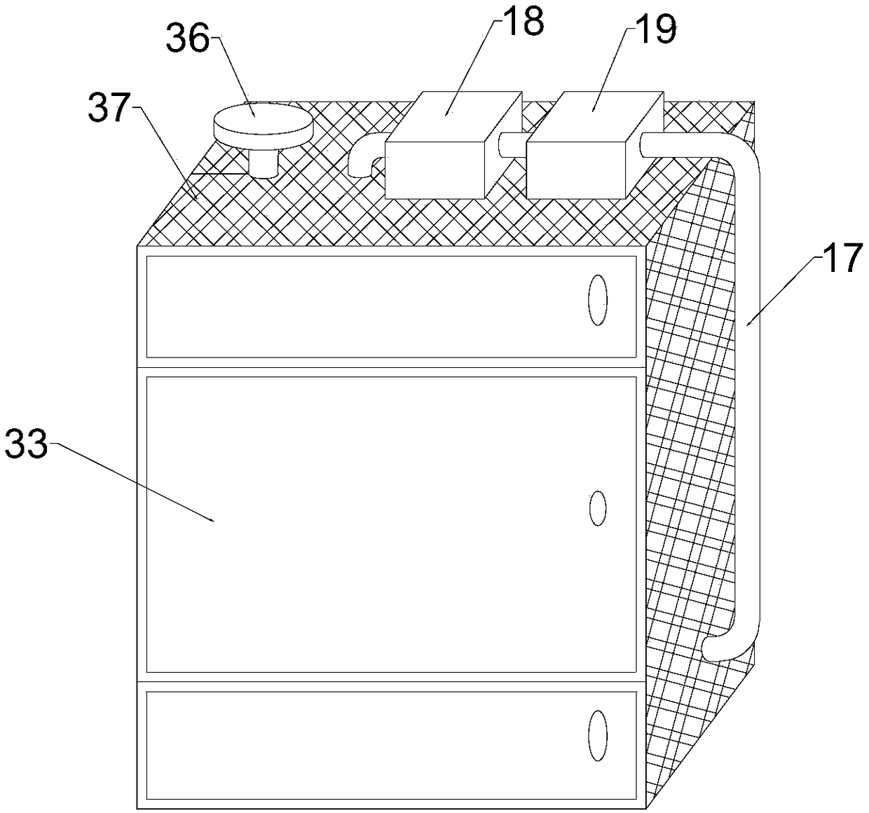
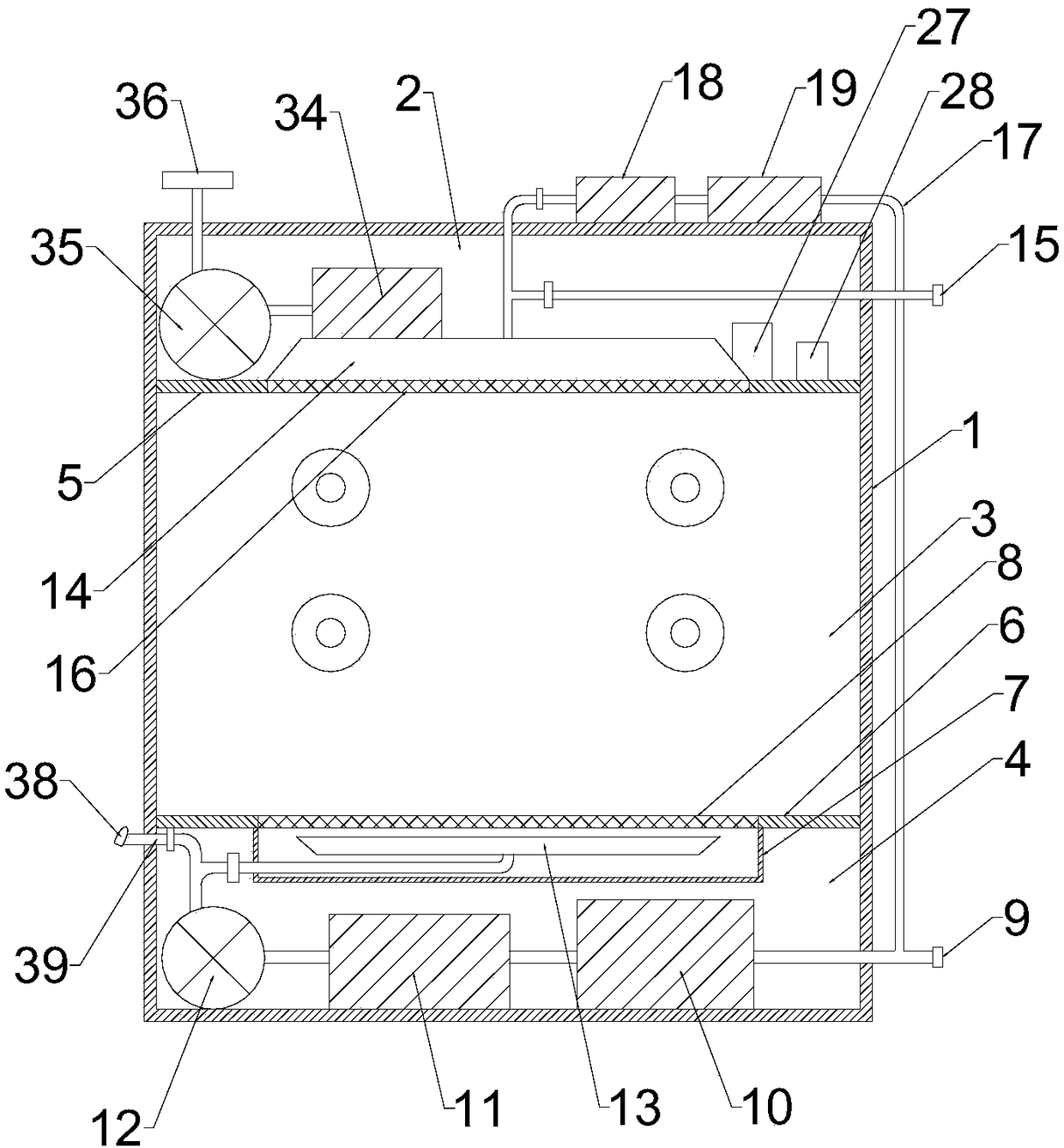
[0035] Such as Figure 1 to Figure 7 As shown, a moisture-proof electrical cabinet includes a cabinet body 1 and a moisture-proof system. The cabinet body 1 is provided with an upper component room 2, an equipment room 3 and a lower component room 4 sequentially from top to bottom. The upper component room A first partition 5 is provided between the device room 2 and the equipment room 3, a second partition 6 is provided between the equipment room 3 and the lower component room 4, and the bottom of the second partition 6 is provided with a moisture-proof drying Air chamber 7, the second partition 6 where the top of the moisture-proof dry air chamber 7 is located is provided with a protective net 8, and the moisture-proof system includes an ...


PUM


Abstract

The invention relates to the technical field of electrical equipment, in particular to a dampproof electrical cabinet. The dampproof electrical cabinet comprises a cabinet body and a dampproof system,an upper component room, an equipment room and a lower component room are arranged in the cabinet body, and the dampproof system comprises an air inlet pipe, a first drying filter, a heater, a fan, an air sharing disc, an air suction disc and an air outlet pipe. In the dampproof electrical cabinet, air is introduced by the fan, is dried by an effect of the first drying filter and is filtered, theair is heated, warmed and dried by the heater, is uniformly sprayed out of ventilation holes of the air sharing disc and flows to the equipment room, air in the equipment room is replaced, the replaced air is discharged to an environment by the air outlet pipe, so that original air with relatively large humidity in the equipment room is replaced by the dried and filtered air, a component in the equipment room is effectively prevented from being affected with damp and damaged, the safety of the equipment is improved, and the service lifetime of the equipment is prolonged.

Description

technical field [0001] The invention relates to the technical field of electrical equipment, in particular to a moisture-proof electrical cabinet. Background technique [0002] There are two main dehumidification methods in the existing fully enclosed electrical cabinets: one is to use heating to dehumidify, that is, to use an electric heater to heat the air in the electrical cabinet, because the air temperature in the electrical cabinet increases and the saturated humidity increases, so the relative humidity However, since the electrical cabinet is closed, the moisture cannot be discharged, so the absolute humidity does not change, and the electrical cabinet actually becomes a high-temperature and high-humidity environment, which is not good for the operation of electrical components; the other is to use refrigeration and dehumidification, which will The evaporator is installed in the electrical cabinet, and when the refrigerant evaporates, it absorbs heat, reduces the temp...

Claims


Application Information

Patent Timeline
Patent Type & Authority Applications(China)
IPC IPC(8): H05K7/20H05K5/02
CPCH05K5/0213H05K7/20
Inventor 李斌
Owner 陆牌电气科技有限公司
Why Eureka
Try Eureka