A high-efficiency stamping device for motor back shell processing and its application method

A technology of punching device and rear shell, applied in the field of punching device, can solve the problems of troublesome maintenance and high use cost of the mechanical arm, and achieve the effects of reducing power equipment, improving punching efficiency and reducing cost

Active Publication Date: 2020-05-15
六安市科新生产力促进中心有限公司
View PDF9 Cites 0 Cited by
  • Summary
  • Abstract
  • Description
  • Claims
  • Application Information

AI Technical Summary

Problems solved by technology

[0003] Some existing stamping devices for the back shell of the motor basically adopt the form of a mechanical arm, through which the motor shell can be automatically fed, punched and discharged. very troublesome

Method used


Image

  • A high-efficiency stamping device for motor back shell processing and its application method
  • A high-efficiency stamping device for motor back shell processing and its application method
  • A high-efficiency stamping device for motor back shell processing and its application method

Examples


Embodiment 1

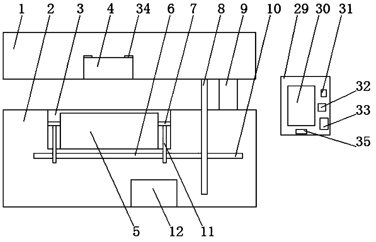
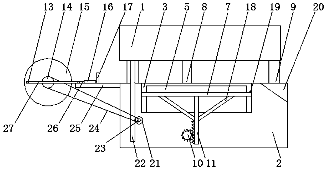
[0027] Embodiment 1, a stamping device for a high-efficiency motor shell equipped with a pressure induction tester, including a stamping base 2, a stamping groove 3 is provided in the middle of the stamping base 2, and a stamping die 5 is provided in the stamping groove 3, so that A top plate 7 is provided between both sides of the stamping die 5 and the stamping groove 3, and the bottom of the top plate 7 is provided with a first fixed rod 11, and the bottom of the first fixed rod 11 is connected to the first rotating shaft 10 through gear engagement. , the upper end of the stamping base 2 is connected to the stamping cover plate 1 through a number of evenly distributed hydraulic rods 9, the middle part of the bottom of the stamping cover plate 1 is provided with a punching machine 4 matching the stamping die 5, and the stamping cover plate 1 One side of the bottom is provided with a fixedly connected first gear bar 8, the bottom of the first gear bar 8 is connected to the fir...

Embodiment 2

[0032]Embodiment 2, a stamping device for a high-efficiency motor shell equipped with a pressure induction tester, including a stamping base 2, a stamping groove 3 is provided in the middle of the stamping base 2, and a stamping die 5 is provided in the stamping groove 3, so that A top plate 7 is provided between both sides of the stamping die 5 and the stamping groove 3, and the bottom of the top plate 7 is provided with a first fixed rod 11, and the bottom of the first fixed rod 11 is connected to the first rotating shaft 10 through gear engagement. , the upper end of the stamping base 2 is connected to the stamping cover plate 1 through a number of evenly distributed hydraulic rods 9, the middle part of the bottom of the stamping cover plate 1 is provided with a punching machine 4 matching the stamping die 5, and the stamping cover plate 1 One side of the bottom is provided with a fixedly connected first gear bar 8, the bottom of the first gear bar 8 is connected to the firs...

Embodiment 3

[0037] Embodiment 3, a stamping device for a high-efficiency motor shell equipped with a pressure induction tester, including a stamping base 2, a stamping groove 3 is provided in the middle of the stamping base 2, and a stamping die 5 is provided in the stamping groove 3, so that A top plate 7 is provided between both sides of the stamping die 5 and the stamping groove 3, and the bottom of the top plate 7 is provided with a first fixed rod 11, and the bottom of the first fixed rod 11 is connected to the first rotating shaft 10 through gear engagement. , the upper end of the stamping base 2 is connected to the stamping cover plate 1 through a number of evenly distributed hydraulic rods 9, the middle part of the bottom of the stamping cover plate 1 is provided with a punching machine 4 matching the stamping die 5, and the stamping cover plate 1 One side of the bottom is provided with a fixedly connected first gear bar 8, the bottom of the first gear bar 8 is connected to the fir...


PUM


Abstract

The invention discloses an efficient stamping device for processing a back shell of a motor and an application method thereof. The device comprises a stamping base, wherein a stamping groove is formedin the middle of the stamping base; a stamping mold is arranged in the stamping groove; an ejecting plate is arranged between two sides of the stamping mold and the stamping groove; a first fixed lever is arranged at the bottom of the ejecting plate; the first fixed rod is connected to a first rotary shaft in a gear engaging form; the upper end of the stamping base is connected to a stamping cover plate through a plurality of uniformly distributed hydraulic rods; a puncher matched with the stamping mold is formed in the middle of the bottom of the stamping cover plate, and first gear racks fixedly connected are arranged on one side of the bottom of the stamping cover plate; by combining the stamping groove and the ejecting plate, the ejecting plate is driven by the gear to ascend and descend by lifting the cover plate to combine and separate the motor shell and a fixed block, so that the power equipment of an original ejecting mechanism is eliminated, and the cost is greatly lowered.The design is simple to operate, high in comprehensive practicality and easy to popularize and use.

Description

Technical field: [0001] The invention relates to a punching device, in particular to a high-efficiency punching device for processing a motor back shell and a method for using the same. Background technique: [0002] Stamping is a forming processing method that applies external force to plates, strips, pipes and profiles by presses and molds to cause plastic deformation or separation to obtain workpieces (stamping parts) of required shape and size. Stamping and forging belong to plastic processing (or pressure processing) and are collectively called forging. The blanks for stamping are mainly hot-rolled and cold-rolled steel sheets and strips. Stamping processing is a production technology that uses the power of conventional or special stamping equipment to directly subject the sheet to deformation force and deform in the mold, so as to obtain product parts of a certain shape, size and performance. Sheet metal, mold and equipment are the three elements of stamping processi...

Claims


Application Information

Patent Timeline
Patent Type & Authority Patents(China)
IPC IPC(8): B21D22/02B21D37/10B21D43/02B21D45/02B21C51/00
CPCB21C51/00B21D22/02B21D37/10B21D43/02B21D45/02
Inventor 朱义付
Owner 六安市科新生产力促进中心有限公司
Why Eureka
Try Eureka