Highway bridge reinforcing device

A reinforcement device and technology for highway bridges, applied in bridge reinforcement, bridges, bridge maintenance, etc., can solve the problems of cumbersome and laborious installation, and achieve the effect of rapid reinforcement, convenient installation and simple structure

Active Publication Date: 2018-09-11
张晓强 +9
View PDF7 Cites 8 Cited by
  • Summary
  • Abstract
  • Description
  • Claims
  • Application Information

AI Technical Summary

Problems solved by technology

[0003] After searching, the authorized announcement number is CN205857260U, which discloses a highway bridge pile foundation reinforcement device, including fixing bolts, intelligent hydraulic pressure, thickened base, supporting load bearing, rubber filler, bearing shaft and connecting steel plate, the fixing Bolts pass through the supporting steel plate to connect with the reinforced pile foundation, the intelligent hydraulic device is provided with a pressure rod, the support platform is connected with a thickened steel cylinder, and the right end of the thickened base is provided with a supporting steel column, And the supporting steel column and the thickened steel cylinder are connected by inclined steel beams, the supporting load bearing is connected with the supporting steel plate, the lower end of the rubber filler is provided with a steel plate, and the upper end is provided with a sealing plate, the The connecting steel plate is connected to the load-bearing shaft, and there is a connecting interface on it, but when the bridge is reinforced, bridges with different heights need to be configured before installation, which is cumbersome and laborious to install , so we propose a highway bridge reinforcement device to solve the above problems

Method used


Image

  • Highway bridge reinforcing device
  • Highway bridge reinforcing device
  • Highway bridge reinforcing device

Examples


Embodiment

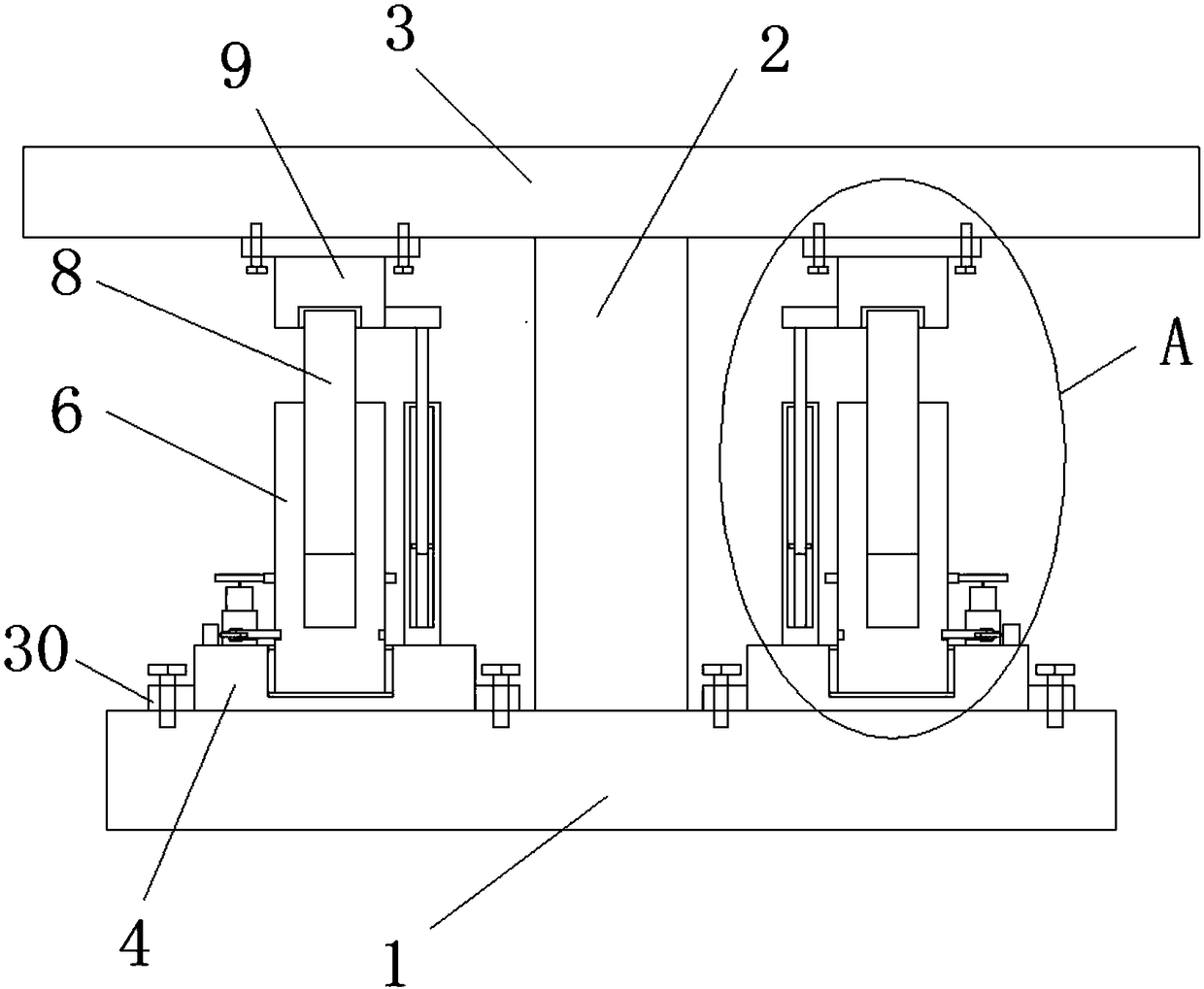
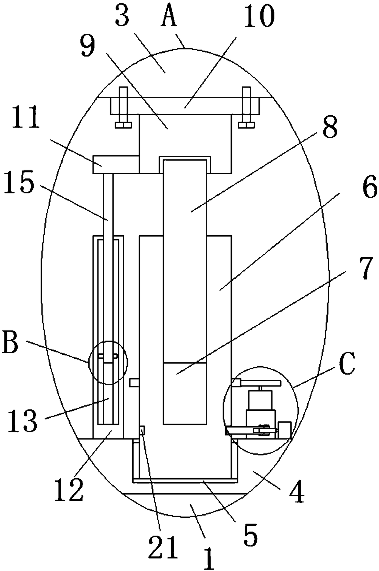
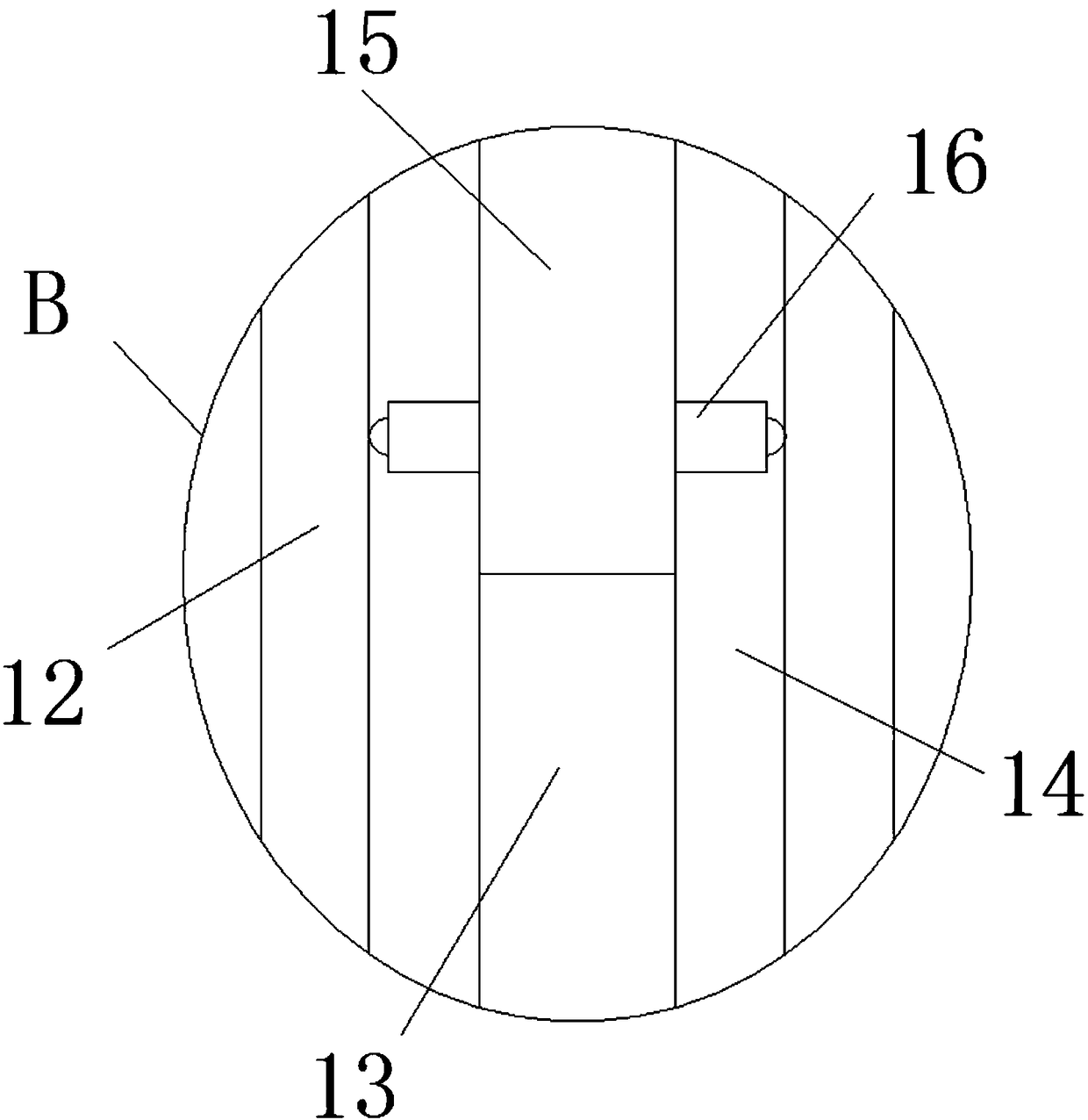
[0017] refer to Figure 1-5 , a highway bridge reinforcement device is proposed in the present embodiment, comprising a bridge base 1, a bridge support column 2 is provided on the top of the bridge base 1, a bridge plate 3 is provided on the top of the bridge support column 2, and a bridge support column 2 is provided on the top of the bridge support column 2 Both sides are provided with the first supporting seat 4 at the top of the bridge base 1, and the top of the first supporting seat 4 is provided with a first groove 5, and the first supporting column 6 is installed in the first groove 5, and the first The top of the support column 6 is provided with a first threaded groove 7, the first threaded groove 7 is internally threaded with a second support column 8, and the top of the second support column 8 is fixedly equipped with a first support block 9, the first support block The top of 9 is fixedly installed with the second support seat 10 that contacts with the bottom of br...


PUM


Abstract

The invention discloses a highway bride reinforcing device. Bridge bases are included, bridge supporting columns are arranged on the tops of the bridge bases, bridge plates are arranged on the tops ofthe bridge supporting columns, first supporting seats, located on the tops of the bridge bases, are arranged on two sides of the bridge supporting columns, first grooves are formed in the tops of thefirst supporting seats, first supporting columns are rotatably installed in the first grooves, first threaded grooves are formed in the tops of the first supporting columns, second supporting columnsare in threaded installation in the first threaded grooves, first supporting blocks are fixedly installed on the tops of the second supporting columns, second supporting seats which are in contact with the bottoms of the bridge plates are fixedly installed on the tops of the first supporting blocks, second supporting blocks are fixedly installed on the sides, close to the bridge supporting columns, of the first supporting blocks, and first supporting rods which are fixedly installed on the tops of the first supporting seats are arranged below the second supporting blocks. The device is simplein structure and convenient to install, and reinforcement can be conducted on bridges of different heights rapidly.

Description

technical field [0001] The invention relates to the technical field of bridges, in particular to a road bridge reinforcement device. Background technique [0002] Bridges generally refer to structures erected on rivers, lakes, and seas to allow vehicles and pedestrians to pass smoothly. In order to adapt to the modern high-speed development of the transportation industry, bridges are also extended to cross mountains, poor geology, or meet other traffic needs to make traffic more convenient. Bridges are generally composed of superstructure, substructure, supports and auxiliary structures. The superstructure is also called bridge span structure, which is the main structure for crossing obstacles; the substructure includes abutments, piers and foundations; The force transmission device installed at the supporting place between the span structure and the bridge pier or abutment; the auxiliary structures refer to the bridge head board, conical slope protection, bank revetment, di...

Claims


Application Information

Patent Timeline
Patent Type & Authority Applications(China)
IPC IPC(8): E01D22/00
CPCE01D22/00
Inventor 张晓强傅海龙张晓华吕珩张云徐倩胡刚领徐振强李晓宗谭晶晶
Owner 张晓强
Why Eureka
Try Eureka