
Method and device for measuring deformation strain gradient of component

A technology of strain gradient and measuring components, which is applied in the direction of measuring devices, optical devices, instruments, etc., can solve the problems of complex installation of measuring equipment, high cost, large error of measurement results, etc., and achieve the effect of simple and fast calculation method

Active Publication Date: 2018-09-11
ZHONGYUAN ENGINEERING COLLEGE
View PDF9 Cites 0 Cited by
  • Summary
  • Abstract
  • Description
  • Claims
  • Application Information

AI Technical Summary

Problems solved by technology

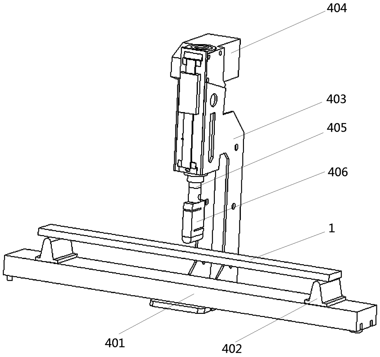
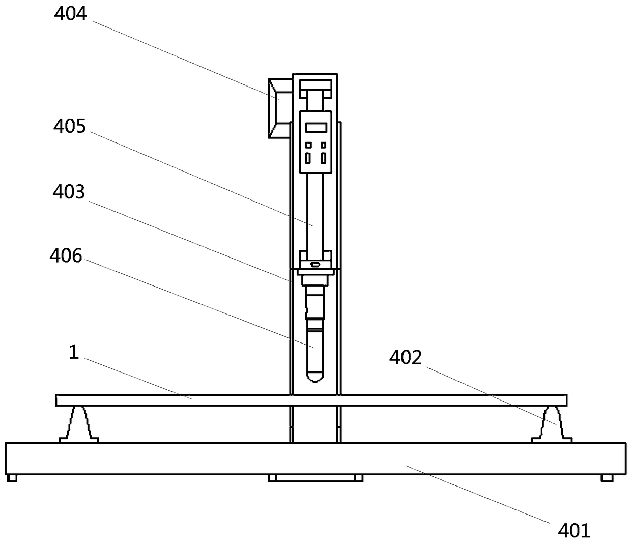
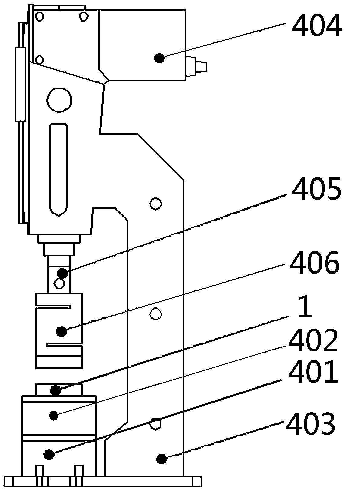
[0004] In view of the deficiencies in the above-mentioned background technology, the present invention proposes a method and device for measuring the deformation and strain gradient of components, which solves the technical problems of complicated installation of measuring equipment, high cost and large error in measurement results in the prior art when measuring structural deformation and strain gradients

Method used


Image

  • Method and device for measuring deformation strain gradient of component
  • Method and device for measuring deformation strain gradient of component
  • Method and device for measuring deformation strain gradient of component

Examples


Embodiment 2

[0098] Embodiment 2, a method for measuring the deformation strain gradient of a component, the simply supported beam 1 is a continuous, uniform, linear elastic isotropic body. Other steps in this embodiment are the same as in Embodiment 1. The method of the invention is more accurate and reliable in monitoring the strain gradient of the isotropic body.

Embodiment 3

[0099]Embodiment 3, a method for measuring the strain gradient of member deformation, the method of the present invention can not only measure the strain gradient of the simply supported beam 1 described in Embodiment 1, but also be applicable to the measurement of the strain gradient of cantilever beams and outrigger beams . Other steps in this embodiment are the same as in Embodiment 1.

Embodiment 4

[0100] Embodiment 4, a method for measuring the deformation and strain gradient of a component. When pasting two groups of fiber grating sensors 2, it should be ensured that the two measuring points of each group of fiber grating sensors 2 are located in the same measurement plane, and each group of fiber grating sensors 2 The arrangement position of is symmetrical with respect to the pressure point of the member. Other steps in this embodiment are the same as in Embodiment 1. The two measuring points of each group are set in the same measuring plane, and the two measuring points of each group will be symmetrical about the pressure point, which can be compared with each other to further ensure the accuracy of the measurement structure.


PUM


Abstract

The invention discloses a device for measuring the deformation strain gradient of a component, which resolves the problems of the prior art that measurement equipment is complex in installation, highin cost and large in measurement result error when the deformation strain gradient of the component is measured. The system comprises a bending machine and a detection system, wherein the detection system comprises a strain gradient measuring unit, a data acquisition and sending unit and a back-end server. The gradient analysis software and background display BS framework software are written in the back-end server, and the rear-end server performs online implementation on receiving, storage, processing, analysis, alarm and visual displaying and the like of deformation strain gradient monitoring data of the component. The invention further discloses a method for measuring the deformation strain gradient of the component. According to the invention, only a simple grating material parametermeasurement test and spectral data analysis before and after component deformation are needed, so that more accurate structural member strain gradient data can be obtained through calculation, the calculation method is simple and rapid, and the method is mainly used for measuring the strain gradient of isotropic material components such as concrete and steel.

Description

technical field [0001] The invention relates to the technical field of engineering mechanics testing, in particular to a method and a device for measuring deformation and strain gradients of components. Background technique [0002] With the continuous development of my country's economy and society, the scale of civil engineering construction has gradually expanded, and the volume and complexity of various structures have steadily increased. The health monitoring of engineering structures has become an increasingly important research. The health of major civil engineering structures such as long-span bridges, dams, long-span spatial structures, super high-rise buildings, and offshore platforms is directly related to the safety of people's lives and property and the normal operation of the national economy. Therefore, monitoring the health status of the structure in time and repairing the early damage of the structure can ensure the performance of the structure, prolong the ...

Claims


Application Information

Patent Timeline
IPC IPC(8): G01B11/16
CPCG01B11/18
Inventor 孙玉周吕娜许君风王锦燕李新明田国环张欣侯东昌胡莹莹
Owner ZHONGYUAN ENGINEERING COLLEGE
Learn More