Heat supply unit thermoelectric cost allocation method

A technology for cost allocation and heating units, applied in data processing applications, marketing, instruments, etc., can solve the problems of calculating the standard coal consumption rate of power supply, etc., and achieve the effect of simple calculation method, small interference factors, and comprehensive consideration

Pending Publication Date: 2022-01-14
华能(广东)能源开发有限公司海门电厂 +1
View PDF0 Cites 0 Cited by
  • Summary
  • Abstract
  • Description
  • Claims
  • Application Information

AI Technical Summary

Problems solved by technology

[0003] The steam generated by the cogeneration unit boiler is not only used for power generation, but also for external heating by means of steam extraction and back pressure. The standard coal consumption rate for power supply (hereinafter referred to as heating coal consumption) cannot be directly measured by belt scales. The value and other data are obtained by using the positive balance method, which can only be calculated according to the external heat supply, boiler efficiency, and pipeline efficiency, or the method of artificially dividing the standard coal volume of the boiler by using the power generation and heat supply sharing ratio.

Method used


Image

  • Heat supply unit thermoelectric cost allocation method
  • Heat supply unit thermoelectric cost allocation method
  • Heat supply unit thermoelectric cost allocation method

Examples


Embodiment 1

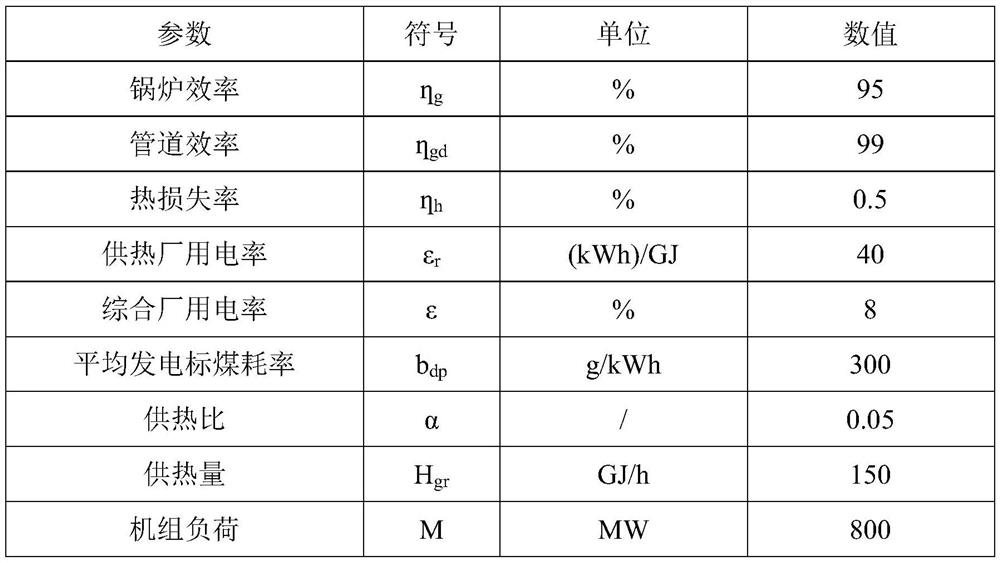
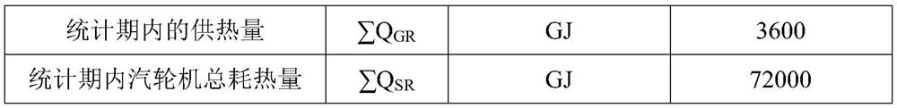
[0072] Embodiment 1 is the operating data of a certain coal-fired cogeneration unit, as shown in the following table:

[0073]

[0074]

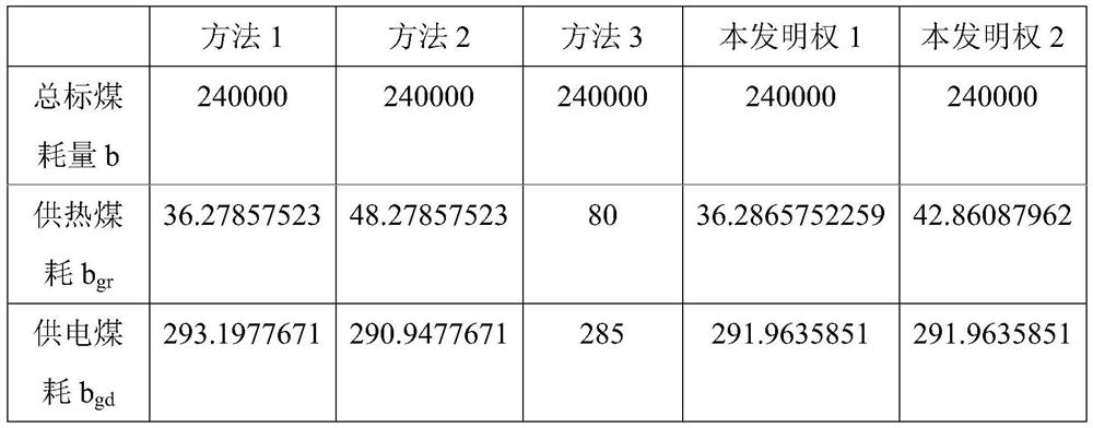
[0075] By above-mentioned apportionment method 1,2,3 and the present invention claim 1 and claim 2 formula calculation results are as follows:

[0076]

[0077] Among them, method 1 has low coal consumption for heating and high coal consumption for power supply, and the benefits are heat;

[0078] Method 2 takes into account the impact of heat supply on plant power points;

[0079] Method 3: Heating coal consumption is high, power supply coal consumption is low, and the benefits go to electricity;

[0080] Claim 1 of the present invention: this embodiment is a coal-fired cogeneration unit, which not only considers the impact of plant power on coal consumption, but also considers the heat supply ratio factor, and the result is between method 1 and method 2;

[0081] Claim 2 of the present invention incorporates the heat loss rate, ...

Embodiment 2

[0083] Embodiment 2 is the operating data of a certain gas-fired unit, as shown in the following table:

[0084]

[0085]

[0086] By above-mentioned apportionment method 1,2,3 and the present invention claim 1 and claim 2 formula calculation results are as follows:

[0087]

[0088] Among them, method 1 has low coal consumption for heating and high coal consumption for power supply, and the benefits are heat;

[0089] Method 2 takes into account the impact of heat supply on plant power points;

[0090] Method 3: Heating coal consumption is high, power supply coal consumption is low, and the benefits go to electricity;

[0091] Claim 1 of the present invention: this embodiment is a gas-fired unit, and the heat loss rate is relatively high. That is, considering the impact of power consumption on coal consumption and the heat supply ratio factor, the result is between method 1 and method 2;

[0092] Claim 2 of the present invention includes the heat loss rate, that is...


PUM


Abstract

The invention relates to the technical field of power plant thermoelectric cost apportionment calculation, in particular to a heat supply unit thermoelectric cost apportionment method. According to the power supply and heat supply cost allocation method provided by the invention, factors influencing coal consumption calculation, such as heat supply meter metering errors and fire coal heat value test errors, are comprehensively considered, reasonable allocation is carried out in heat supply and power generation links, and auxiliary power, heat supply and power generation cost and the like can be allocated by utilizing a heat supply ratio; various methods for calculating the heat supply cost of the current domestic heat supply unit are fully combined, and the cost allocation calculation method is perfected and corrected; the result meets the actual conditions of various types of units, and the method is extremely high in universality and has good expansibility.

Description

technical field [0001] The present invention relates to the technical field of thermal power cost apportionment calculation in power plants, and more specifically, relates to a thermal power cost apportionment method for heating units. Background technique [0002] The fuel consumption of cogeneration units is not completely consistent with the power generation capacity: part of the fuel consumption of this type of unit is used for grid power generation, while the other part is used for heating. The accuracy of the actual power consumption data of cogeneration units directly affects the electricity market quotation strategy and profitability of this type of units. Therefore, it is necessary to provide scientific and effective calculation methods for the "coal consumption calculation of power supply" of cogeneration units. [0003] The steam generated by the cogeneration unit boiler is not only used for power generation, but also for external heating by means of steam extract...

Claims


Application Information

Patent Timeline
Patent Type & Authority Applications(China)
IPC IPC(8): G06Q10/06G06Q30/02G06Q50/06
CPCG06Q10/0639G06Q30/0206G06Q50/06Y02E20/14Y04S50/14
Inventor 刘安仓黄和龙谢颖纨朱晨亮陈韶华胡立川朱元磊
Owner 华能(广东)能源开发有限公司海门电厂
Why Eureka
Try Eureka