Method for improving selective laser cladding NiTi performance by controlling parameters

A technology of laser selective cladding and parameter control, applied in the field of material 3D printing, to achieve the effects of excellent tensile properties and cycle performance, high safety factor and high degree of automation

Inactive Publication Date: 2021-09-17
JILIN UNIV
View PDF12 Cites 0 Cited by
  • Summary
  • Abstract
  • Description
  • Claims
  • Application Information

AI Technical Summary

Problems solved by technology

[0005] Aiming at the deficiencies of the prior art, the present invention provides a method of controlling parameters to improve the performance of laser selective cladding NiTi, which has the advantage of optimizing SLM parameters to ensure the optimal forming of NiTi, and solves the problem of designing the forming parameters. question

Method used


Image

  • Method for improving selective laser cladding NiTi performance by controlling parameters
  • Method for improving selective laser cladding NiTi performance by controlling parameters
  • Method for improving selective laser cladding NiTi performance by controlling parameters

Examples


Embodiment 1

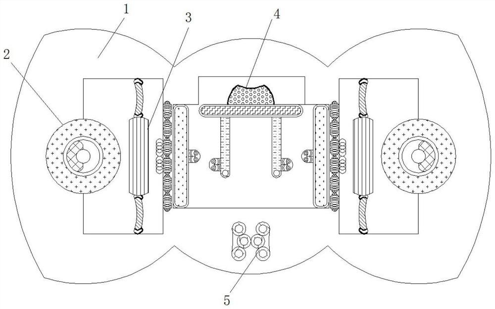
[0040] see Figure 1-2 , a vacuum dryer used in the production process as described above, including a device housing 1, and also includes an electromagnetic wave detection component 2, a vibration sensing component 3, and a humidity sensing component 4, and the electromagnetic wave detection component 2 is fixedly connected inside the device housing 1 , used to detect the strength of the electromagnetic field where the vacuum drying equipment is located. The vibration sensing component 3 is fixedly connected to the inside of the equipment casing 1, and is used to detect the ambient humidity of the vacuum drying equipment. The inside of the equipment casing 1 is fixedly connected to a humidity sensing component 4 , used to detect whether the vacuum drying equipment is in a state of severe vibration;

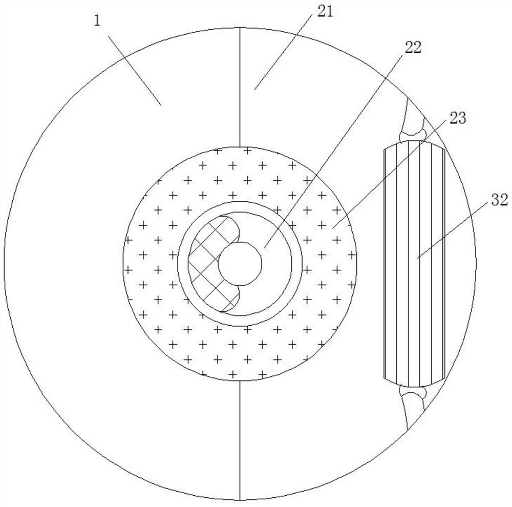
[0041]The electromagnetic wave detection component 2 includes a mounting groove 21, a thermistor 22, and a wave-absorbing material 23. The inside of the equipment housing 1 is pr...

Embodiment 2

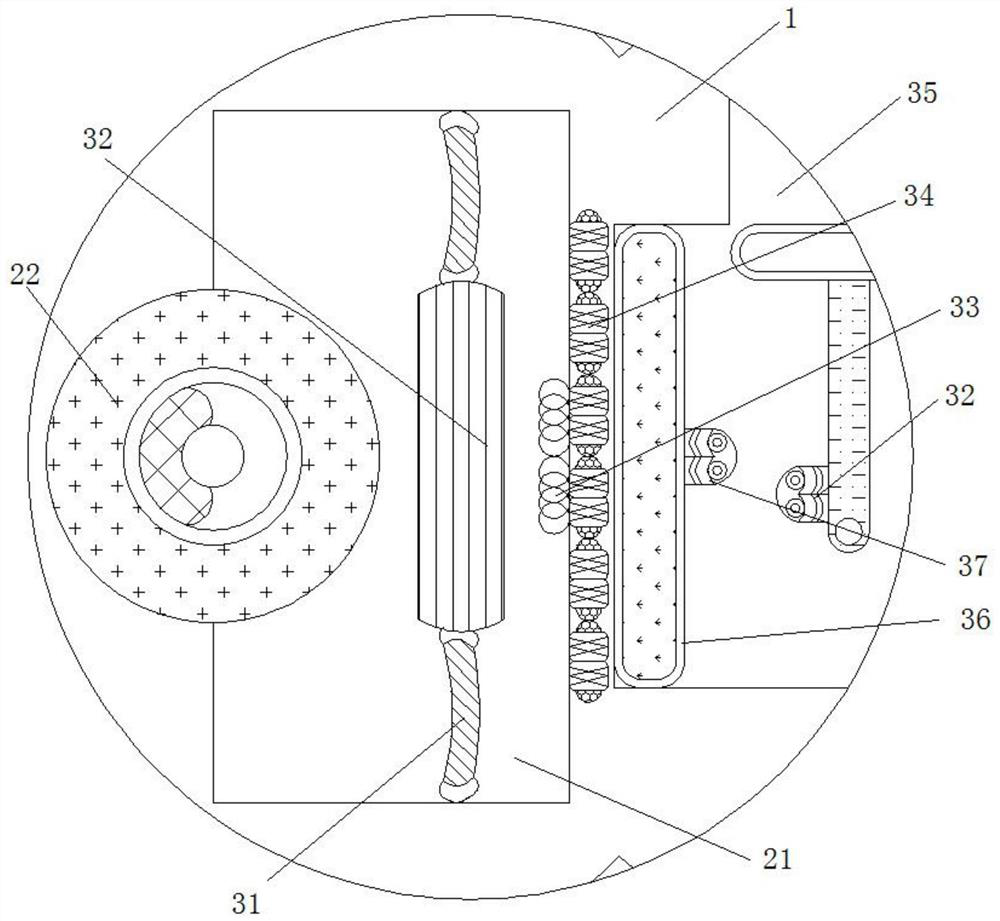
[0043] see Figure 1-4 , a vacuum dryer used in the production process as described above, including a device housing 1, and also includes an electromagnetic wave detection component 2, a vibration sensing component 3, and a humidity sensing component 4, and the electromagnetic wave detection component 2 is fixedly connected inside the device housing 1 , used to detect the strength of the electromagnetic field where the vacuum drying equipment is located. The vibration sensing component 3 is fixedly connected to the inside of the equipment casing 1, and is used to detect the ambient humidity of the vacuum drying equipment. The inside of the equipment casing 1 is fixedly connected to a humidity sensing component 4 , used to detect whether the vacuum drying equipment is in a state of severe vibration;

[0044] The electromagnetic wave detection component 2 includes a mounting groove 21, a thermistor 22, and a wave-absorbing material 23. The inside of the equipment housing 1 is p...


PUM

PropertyMeasurementUnit
particle sizeaaaaaaaaaa

Abstract

The invention relates to the technical field of material 3D printing, and discloses a method for improving selective laser cladding NiTi performance by controlling parameters, an SLM processing technology is applied, a material is directly formed, secondary machining is avoided on NiTi alloy difficult to machine, a parameter design scheme is obtained according to an orthogonal table, parameters are set step by step according to the scheme through a BLT-S210 type laser, and a cuboid block is printed through the laser according to set parameters. According to the method for improving the selective laser cladding NiTi performance by controlling the parameters, due to the fact that the SLM preparation technology is adopted, the NiTi alloy can be directly formed, the trouble of secondary machining is omitted, the parameter selection range is wider than the single-factor change range, factor consideration is more comprehensive, the relation between the parameters and the phase change temperature of a phase change material can be found out through parameter design, therefore, parameter control phase change is achieved, the printed and formed material has excellent tensile property and cycle performance, and the cycle tensile fracture strain of an optimal sample can reach 10%.

Description

technical field [0001] The invention relates to the technical field of material 3D printing, in particular to a method for controlling parameters to improve the performance of laser selective cladding NiTi. Background technique [0002] At present, domestic NiTi processing is prepared by traditional smelting, and the desired structure is obtained through secondary processing. However, due to the high ductility and strong work hardening of NiTi alloy, it brings difficulties to the secondary processing and limits its use. application, and now, the method of additive manufacturing is gradually entering people's field of vision, and its direct forming method can just solve the difficulty of secondary processing of NiTi alloy, providing a broader platform for the application of NiTi alloy, but due to its processing parameters Seriously affect the phase change characteristics, mechanical properties, and molding quality of this material, so controlling parameters to adjust the mold...

Claims


Application Information

Patent Timeline
Patent Type & Authority Applications(China)
IPC IPC(8): C23C24/10B22F1/00B22F10/28B22F12/00B33Y10/00B33Y40/10B33Y70/00C22C19/03
CPCC23C24/106B22F10/28B22F12/00C22C19/03B33Y10/00B33Y40/10B33Y70/00Y02P10/25
Inventor 于征磊徐泽洲沙鹏威曹青李伦翔信仁龙陈立新郭雪李建勇张志辉
Owner JILIN UNIV
Why Eureka
Try Eureka