Supercharge Your Innovation With Domain-Expert AI Agents!

Compaction test apparatus

A compaction instrument and workbench technology, applied in the field of compaction instruments, can solve the problems of reducing the use efficiency of the compaction instrument, increasing the adjustment time, and difficult to support the synchronous rotation of the cylinder, so as to reduce labor intensity, improve use efficiency, The effect of comfortable movement

Inactive Publication Date: 2018-09-11
浙江裕立检测科技有限公司
View PDF5 Cites 2 Cited by
  • Summary
  • Abstract
  • Description
  • Claims
  • Application Information

AI Technical Summary

Problems solved by technology

However, in the process of the user manually rotating the support cylinder, it is difficult to ensure that the two support cylinders rotate synchronously, that is to say, the movement of the sample mold support frame will be stuck, which will increase the time for moving and adjusting the sample mold support frame , which reduces the efficiency of the compaction instrument to a certain extent

Method used


Image

  • Compaction test apparatus
  • Compaction test apparatus
  • Compaction test apparatus

Examples


Embodiment Construction

[0029] The present invention will be described in further detail below in conjunction with the accompanying drawings.

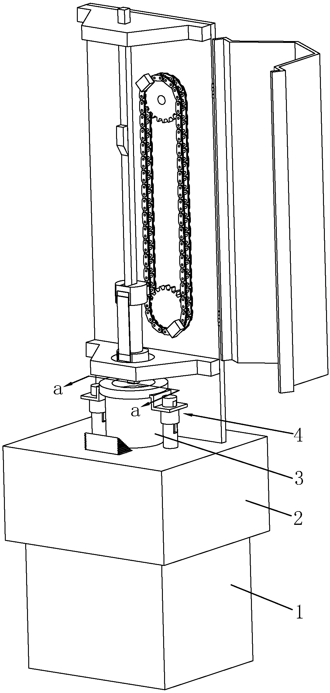
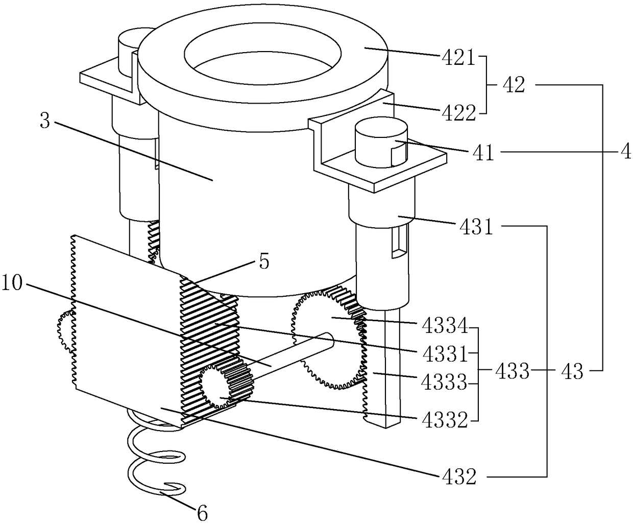
[0030] A compactor such as figure 1 , figure 2 As shown, it includes a frame 1 , a workbench 2 arranged on the frame 1 , a sample mold 3 placed on the workbench 2 , and a fixing mechanism 4 arranged on the workbench 2 . The workbench 2 is fixedly connected with the frame 1 by welding, and the top surface of the workbench 2 is a horizontal plane. An abutment block 11 is arranged on the top surface of the workbench 2 , and an arc-shaped groove 12 is arranged on the side wall of the abutment block 11 . The sample mold 3 is cylindrical, and the end surface of the sample mold 3 facing away from the workbench 2 is provided with a placement groove 13 for placing the sample, and the shape of the notch of the placement groove 13 is circular. When the sample mold 3 is located inside the arc-shaped groove 12 , the outer wall of the sample mold 3 is attached to the i...


PUM


Abstract

The invention discloses a compaction test apparatus. The key point of the technical scheme thereof is characterized in that the compaction test apparatus comprises a machine frame, a workbench, a sample mold and a fixing mechanism; the fixing mechanism comprises positioning rods, a positioning frame and a driving mechanism; at least two positioning rods are arranged on the fixing mechanism; the positioning frame is simultaneously slidably connected with all of the positioning rods; the driving mechanism comprises a support cylinder, a triggering rod and a transmission mechanism; the support cylinder sleeves the positioning rods; the triggering rod passes through the interior of the workbench; the transmission mechanism corresponds to the positioning rods one by one; the transmission mechanism comprises a transmission gear, a first gear rotatably connected to the interior of the workbench, and a rack passing through the workbench, in a using process, the sample mold only needs to be placed on the triggering rod, the triggering rod is enabled to be moved to the interior of the workbench, and the triggering rod pushes the positioning frame to be upwards moved through the transmissionmechanism. So the support frame does not need to be adjusted manually, the efficiency is higher. While a sample is detected, a compaction hammer on the compaction test apparatus does not contact withthe positioning frame, and the detection is more accurate.

Description

technical field [0001] The invention relates to the technical field of building detection equipment, in particular to a compaction instrument. Background technique [0002] The compaction instrument is a kind of construction equipment, which is mainly used to determine the optimum moisture content and unit volume weight of compacted soil. [0003] At present, the Chinese patent whose notification number is CN204789091U discloses a Marshall sample electric compactor, which includes a frame and a sample mold fixing mechanism, a workbench is arranged on the frame, and a sample mold is placed on the workbench. The sample mold fixing mechanism includes a sample mold positioning frame and a sample mold positioning rod vertically arranged on the workbench. The sample mold positioning frame includes a sample mold positioning frame for positioning and matching with the upper end of the sample mold and symmetrical fixing The guide plates are arranged on both sides of the sample mold ...

Claims


Application Information

Patent Timeline
IPC IPC(8): G01N1/28G01N33/24
CPCG01N1/286G01N33/24
Inventor 李铭杨菊玲郑镇涛杨性海俞丹敏周家早王琼沈红炎林高伟
Owner 浙江裕立检测科技有限公司
Features
  • R&D
  • Intellectual Property
  • Life Sciences
  • Materials
  • Tech Scout
  • Unparalleled Data Quality
  • Higher Quality Content
  • 60% Fewer Hallucinations
Learn More