Eureka AIR delivers breakthrough ideas for toughest innovation challenges, trusted by R&D personnel around the world.

Device and method for measuring reheating linear shrinkage ratio of ultra-thin glass through laser method

A technology of ultra-thin glass and shrinkage rate, which is applied in the direction of measuring devices, optical devices, and material thermal analysis. Uniform, meet the measurement requirements of the effect

Active Publication Date: 2018-09-11
北京旭辉新锐科技有限公司
View PDF31 Cites 5 Cited by
  • Summary
  • Abstract
  • Description
  • Claims
  • Application Information

AI Technical Summary

Problems solved by technology

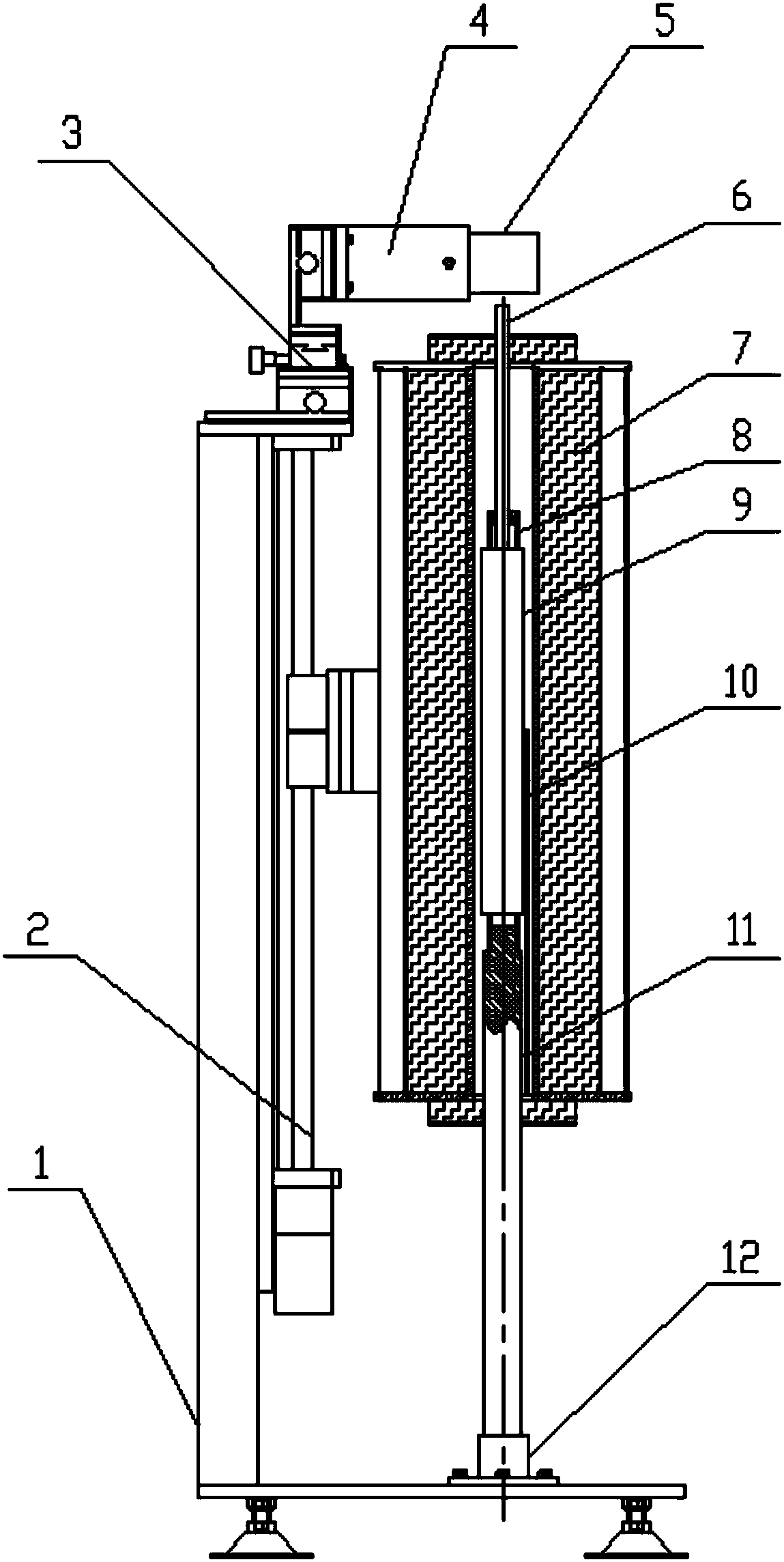
[0010] In order to overcome the problems of poor accuracy, difficult operation, and human-introduced errors in measuring glass shrinkage in the prior art, the present invention proposes a device and method for measuring the reheating shrinkage of ultra-thin glass by laser method. The glass sample is placed in a tubular heating furnace. In the uniform temperature field, ensure that the glass sample is evenly heated; the high-precision laser sensor is used to measure the glass in real time, and the measurement accuracy is high; at the same time, the glass sample does not need to be marked and weighed, and no error will be introduced artificially; L 0 When it is 300mm, the shrinkage rate measurement accuracy can reach 1ppm, which can meet the current LTPS process technology and testing requirements

Method used


Image

  • Device and method for measuring reheating linear shrinkage ratio of ultra-thin glass through laser method
  • Device and method for measuring reheating linear shrinkage ratio of ultra-thin glass through laser method
  • Device and method for measuring reheating linear shrinkage ratio of ultra-thin glass through laser method

Examples


Embodiment Construction

[0032] In order to make the purpose, technical solutions and advantages of the embodiments of the present invention clearer, the technical solutions in the embodiments of the present invention will be clearly and completely described below in conjunction with the drawings in the embodiments of the present invention. Obviously, the described embodiments It is a part of embodiments of the present invention, but not all embodiments. Based on the embodiments of the present invention, all other embodiments obtained by persons of ordinary skill in the art without making creative efforts belong to the protection scope of the present invention.

[0033] In the description of the present invention, it should be noted that the terms "center", "upper", "lower", "left", "right", "vertical", "horizontal", "inner", "outer" etc. The indicated orientation or positional relationship is based on the orientation or positional relationship shown in the drawings, and is only for the convenience of d...


PUM

PropertyMeasurementUnit
thicknessaaaaaaaaaa
lengthaaaaaaaaaa
thicknessaaaaaaaaaa

Abstract

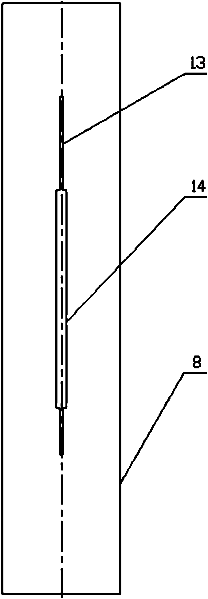
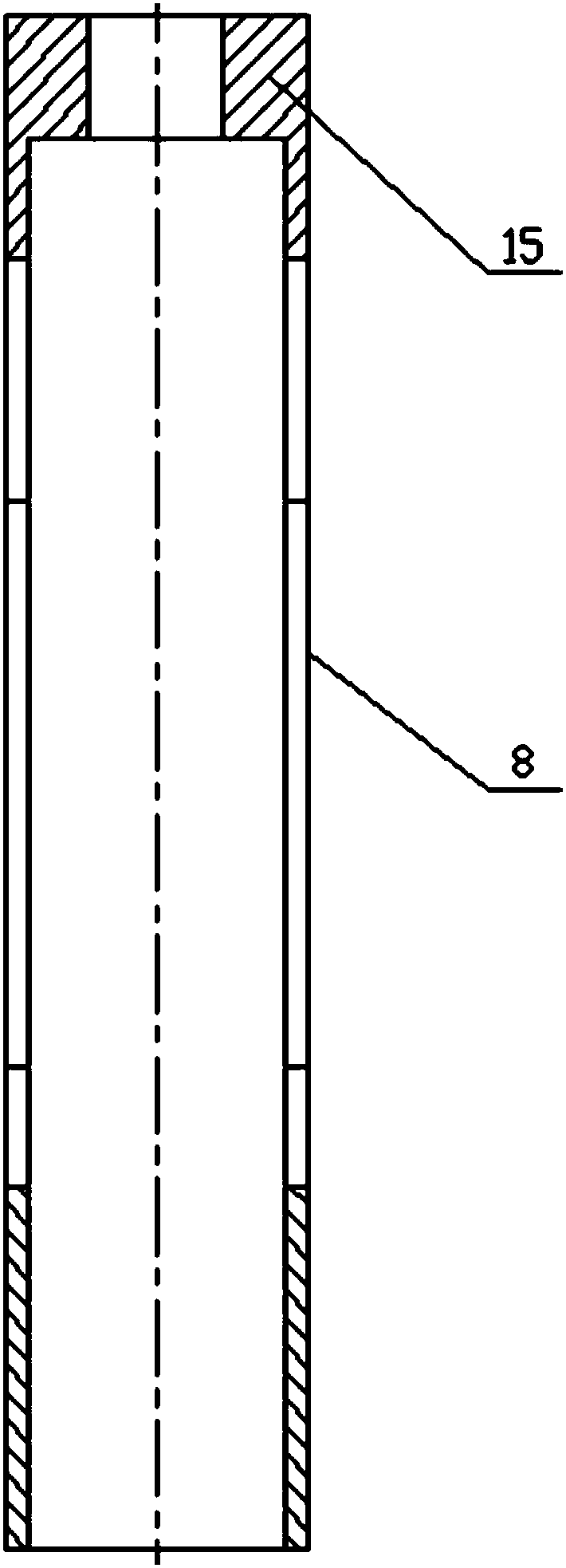
The invention discloses a device and a method for measuring a reheating linear shrinkage ratio of ultra-thin glass through a laser method. The device comprises an L-shaped rack body, a heating furnace, a laser sensor, a quartz support, a quartz pushrod, a quartz rod and the like, wherein an electric lifting mechanism which is used for adjusting top and bottom positions of the heating furnace is mounted on a vertical rack of the L-shaped rack body; an X, Y and Z three-dimensional movable platform which is used for adjusting the laser sensor is mounted on the top of the vertical rack of the L-shaped rack body; when the test is carried out, a glass test sample is put in the special quartz support, and the quartz support is put in the heating furnace, the length shrinkage variation before andafter heating of the glass test sample is monitored by the laser sensor in real time, and the length shrinkage variation is divided by the original length of the glass test sample so as to obtain thereheating linear shrinkage ratio of the glass test sample. According to the device and the method disclosed by the invention, monitoring is carried out by using the high-accuracy laser sensor in realtime, so that the problems of errors caused by a human operation such as a scribing method and low microscopic observation accuracy are avoided, and a relatively simple and feasible testing method anddevice are provided for measuring the ultra-thin glass with the low shrinkage variation ratio of less than or equal to 10ppm.

Description

technical field [0001] The invention relates to the technical field of glass reheat line shrinkage testing, in particular to a device and method for measuring reheat line shrinkage of ultra-thin glass by laser method, which can meet the measurement of reheat line shrinkage of glass substrates for LCD / OLED displays based on LTPS process technology. Background technique [0002] Ultra-thin glass refers to flat glass with a thickness of less than 1.1mm, and one of its important application areas is electronic display products. With the development of LCD / OLED display products in the direction of high resolution, the use of TFTs prepared by Low Temperature Poly-silicon (LTPS) technology enables LCD / OLED display products to have high resolution, fast response speed, high brightness, and aperture ratio. Great advantages. [0003] The LTPS process is to heat-treat the amorphous silicon (a-Si) deposited on the surface of the glass substrate to convert it into polysilicon (Poly-sili...

Claims


Application Information

Patent Timeline
Patent Type & Authority Applications(China)
IPC IPC(8): G01N25/00G01N25/16G01B11/02
CPCG01B11/02G01N25/00G01N25/16
Inventor 田英良陈鑫鑫王为李建峰刘亚茹孙诗兵吕锋相志磊刘岳翔
Owner 北京旭辉新锐科技有限公司
Why Eureka
Eureka Blog
Learn More