Chip radiator pasting mechanism

A heat sink and chip technology, applied in semiconductor/solid-state device manufacturing, electrical components, circuits, etc., can solve problems such as low work efficiency and low product pass rate, and achieve the effect of improving work efficiency and product pass rate

Inactive Publication Date: 2018-09-11
JIANGSU BVM INTELLIGENT TECH
View PDF0 Cites 2 Cited by
  • Summary
  • Abstract
  • Description
  • Claims
  • Application Information

AI Technical Summary

Problems solved by technology

[0003] The purpose of the present invention is to overcome the deficiencies in the prior art, provide a chip heat sink sticking mechanism, and solve the technical problems of low work efficiency and low product qualification rate in the prior art that the chip heat sink adopts manual sticking.

Method used


Image

  • Chip radiator pasting mechanism
  • Chip radiator pasting mechanism

Examples


Embodiment Construction

[0021] The present invention will be further described below in conjunction with the accompanying drawings. The following examples are only used to illustrate the technical solution of the present invention more clearly, but not to limit the protection scope of the present invention.

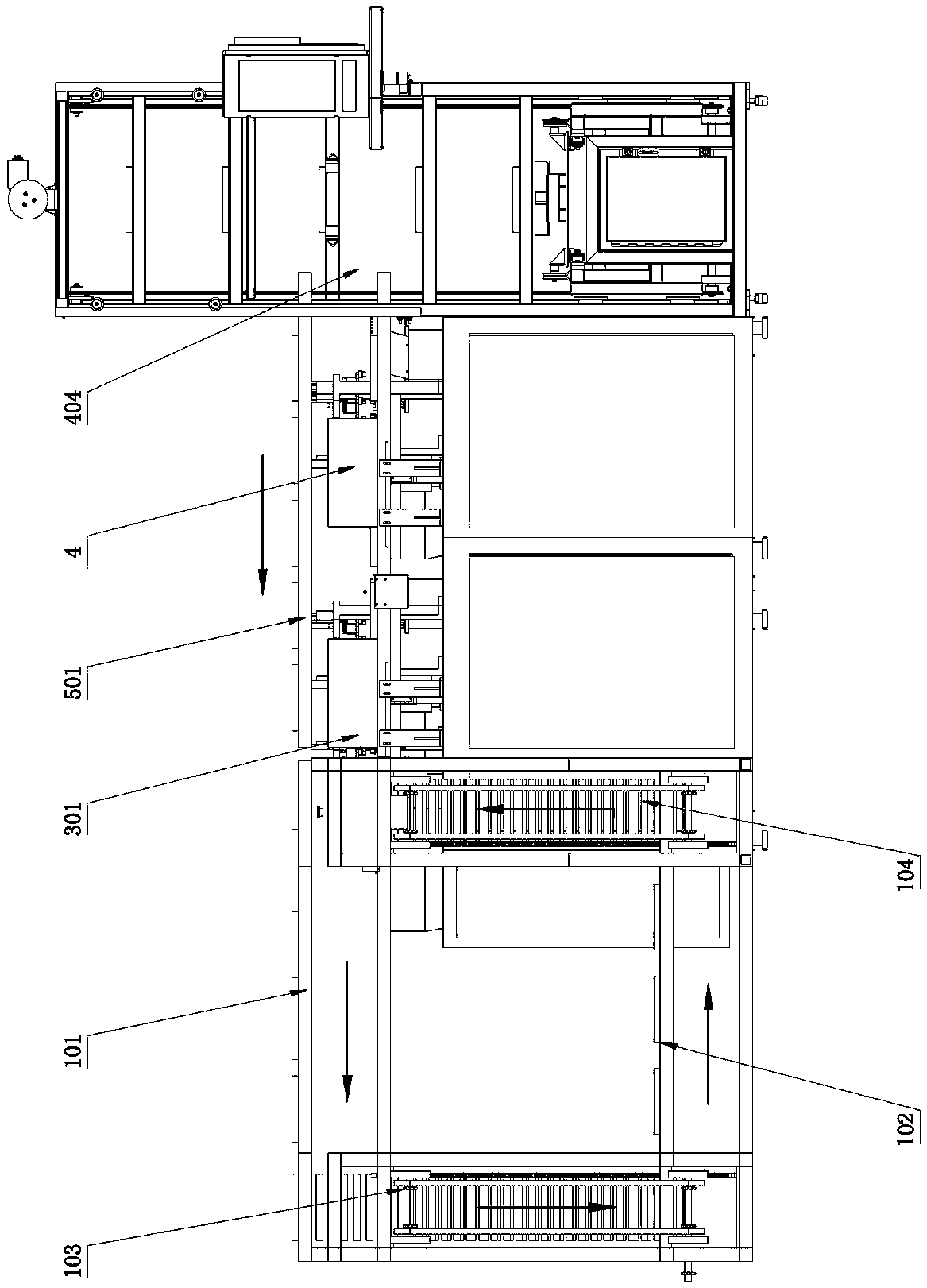
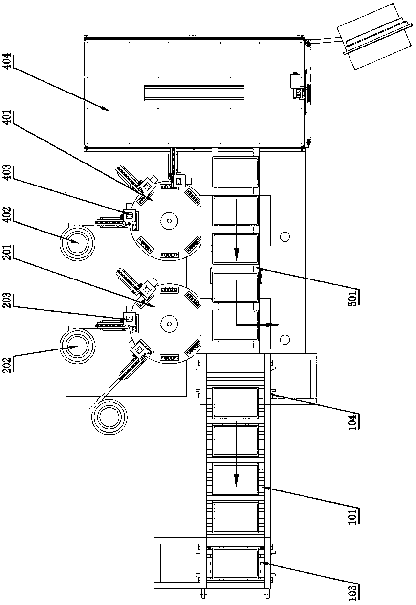
[0022] Such as figure 1 , figure 2 As shown, a chip radiator sticking mechanism 301 includes an integrated circuit board feeding mechanism, a heat sink feeding mechanism, a sticking mechanism 301, a static pressure mechanism 4 and a blanking mechanism;

[0023] The integrated circuit board feeding mechanism includes a first conveying mechanism 101, a second conveying mechanism 102, an unloading elevator 103 and a loading elevator 104, and the second conveying mechanism 102 is located below the first conveying mechanism 101; The circuit boards are laid flat on the first conveying mechanism 101 in sequence, and are transported by the first conveying mechanism 101 to the unloading elevator 103. ...


PUM


Abstract

The invention discloses a chip radiator pasting mechanism. The mechanism comprises an integrated circuit board feeding mechanism, a radiator feeding mechanism, a pasting mechanism, a static pressing mechanism and an unloading mechanism; the pasting mechanism pastes radiators outputted by the radiator feeding mechanism onto a plurality of chips on an integrated circuit board; the static pressing mechanism arranges static pressing blocks on the radiators that have been pasted on the chips; and the unloading mechanism outputs the integrated circuit board onto which the radiators have been pasted.The whole chip radiator pasting process of the chip radiator pasting mechanism of the invention includes integrated circuit board feeding, radiator feeding, pasting, static pressing and unloading which are all automatically completed by a pasting machine; one person can operate the pasting mechanism so as to complete the pasting of the radiators quickly and accurately; and therefore, work efficiency and the yield of production can be significantly improved.

Description

technical field [0001] The invention relates to a chip processing equipment, in particular to a chip radiator sticking mechanism. Background technique [0002] Nowadays, with the advancement of computer technology, the chip is the product of VLSI technology and the core component of the computer. With the development and progress of chip technology, the heating power of chips is increasing, and more and more chips in computers need external equipment to improve heat dissipation efficiency, otherwise they cannot work normally. In the prior art, the pasting of the chip heat sink is usually done manually, which has low work efficiency and low product qualification rate, which seriously affects the production efficiency of the chip. Contents of the invention [0003] The purpose of the present invention is to overcome the deficiencies in the prior art, provide a chip heat sink sticking mechanism, and solve the technical problems of low work efficiency and low product qualific...

Claims


Application Information

Patent Timeline
IPC IPC(8): H01L21/67
CPCH01L21/67132
Inventor 李相鹏
Owner JIANGSU BVM INTELLIGENT TECH
Why Eureka
Try Eureka