Automatic control method for tailstock of numerical control lathe

一种数控车床尾座、数控车床的技术,应用在数控车床领域,能够解决数控机床的尾座不能自动进给、钻孔深度尺寸难以保证、加工效率低等问题,达到提高灵活性、控制钻孔深度、提高自动化程度的效果

Inactive Publication Date: 2018-09-14
赵红艳
View PDF8 Cites 0 Cited by
  • Summary
  • Abstract
  • Description
  • Claims
  • Application Information

AI Technical Summary

Problems solved by technology

[0003] CNC lathe is one of the most commonly used automatic processing equipment in mechanical cutting. However, the tailstock of general CNC machine tools cannot be fed automatically. Therefore, when performing drilling operations on CNC lathes, only the operating handle of the tailstock can be manually rotated. , time-consuming and labor-intensive, it is difficult to guarantee the drilling depth, and the processing efficiency is low

Method used


Image

  • Automatic control method for tailstock of numerical control lathe
  • Automatic control method for tailstock of numerical control lathe
  • Automatic control method for tailstock of numerical control lathe

Examples


Embodiment Construction

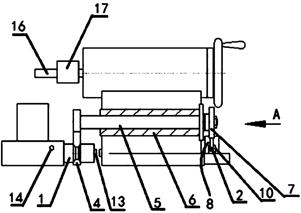
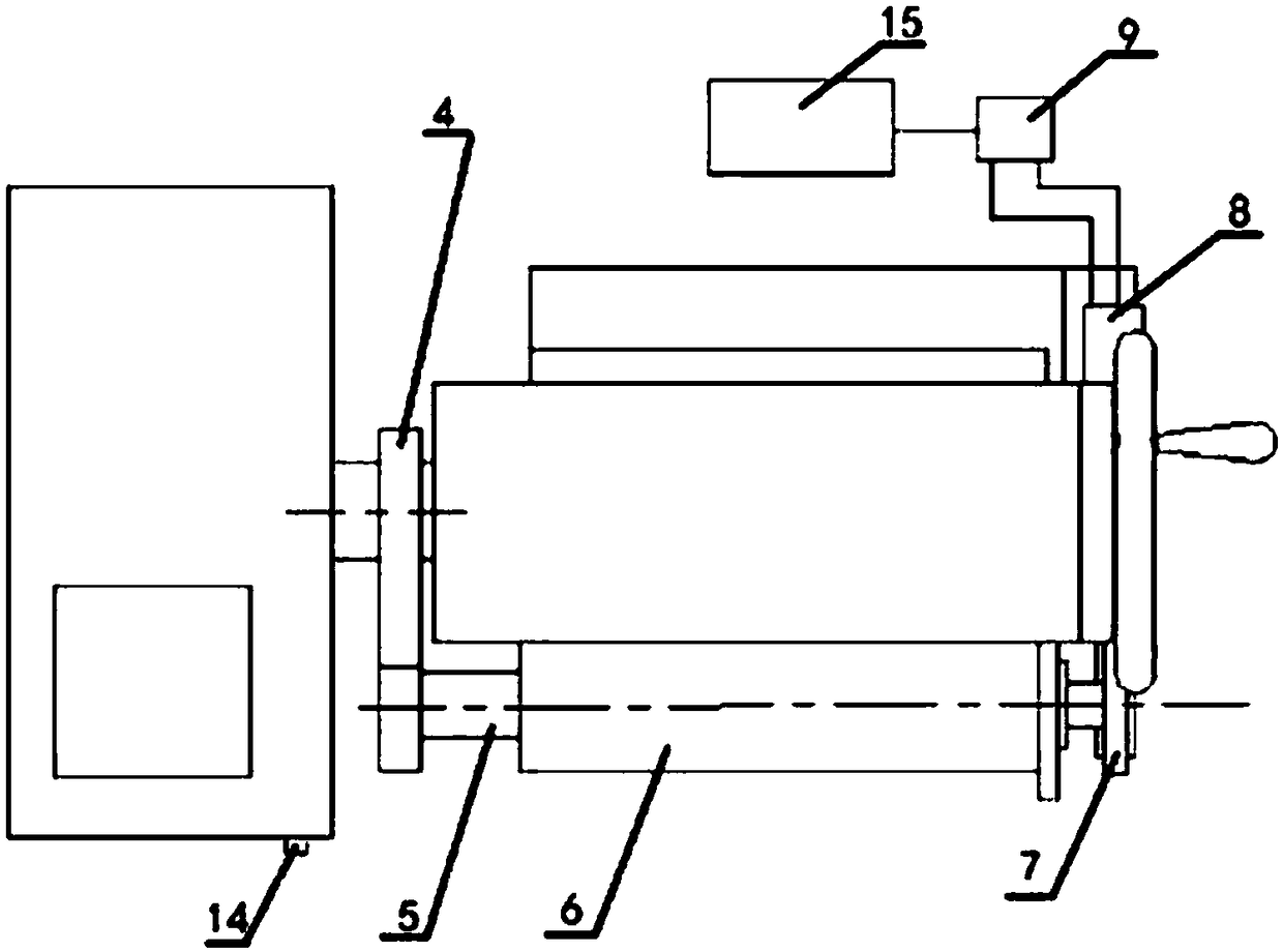
[0021] An automatic control method for a tailstock of a CNC lathe, which uses a cylinder to realize the automatic engagement and disengagement of a saddle and a tailstock of a CNC lathe, and includes a connecting column 1, a rotating arm assembly, a driving assembly and a drill assembly. The middle part of the connecting column 1 is provided with a ring groove 3, the connecting column 1 is fixedly connected with the saddle of the CNC lathe, and a pair of sensors 13 are arranged on the shaft end of the connecting column 1 and the side of the tailstock, and the sensors can be magnetic effect sensors or Hall effect sensors. The sensor can also be a photoelectric sensor.

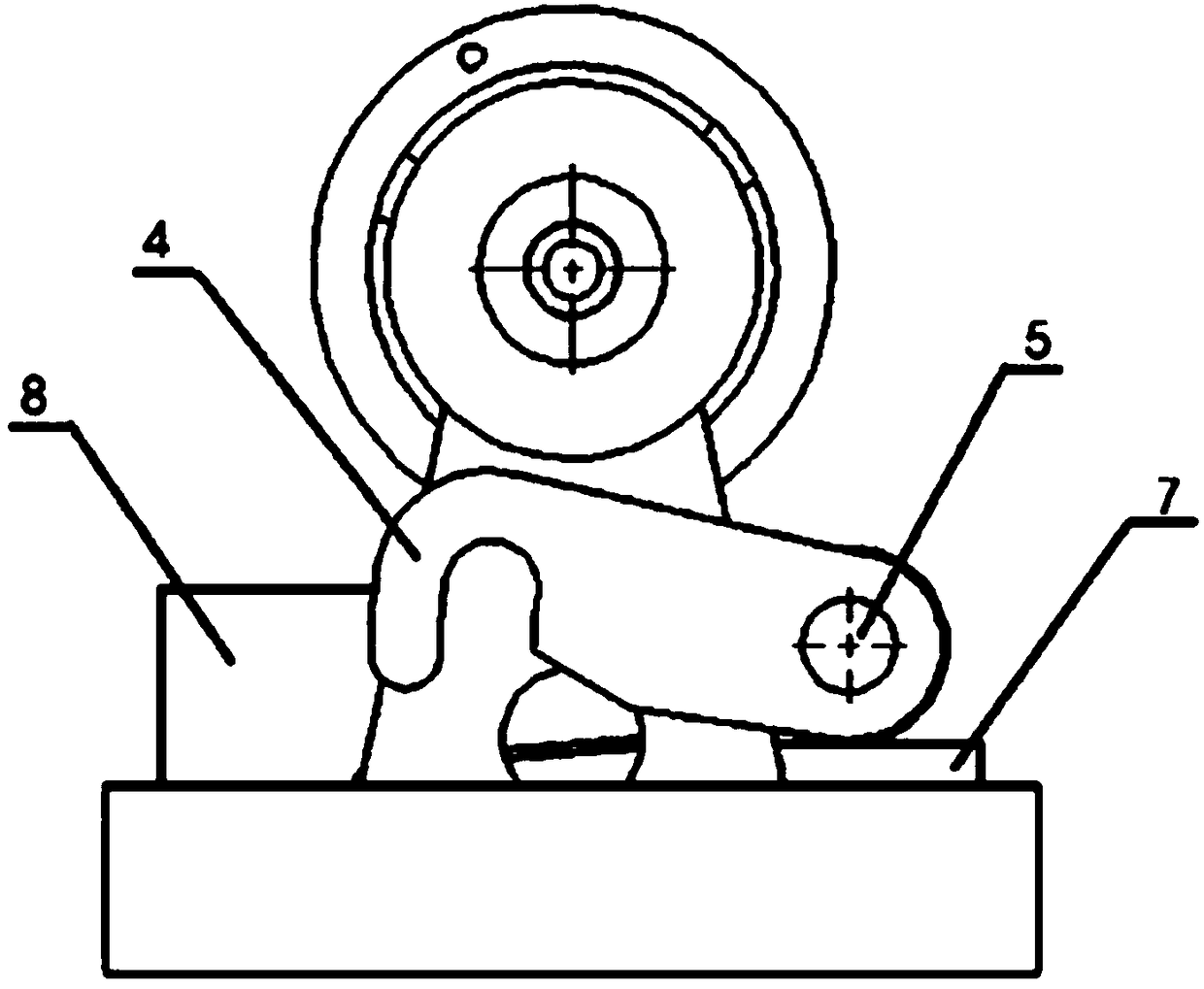
[0022] Described rotating arm assembly comprises rotating arm 4, rotating shaft 5, axle sleeve 6 and bull gear 7, and described axle sleeve 6 is fixed on the front side of CNC lathe tailstock, and described rotating shaft 5 passes through axle sleeve 6, and rotates The front end of the shaft 5 is fixedly connect...


PUM


Abstract

The invention provides an automatic control method for a tailstock of a numerical control lathe, and discloses a connecting device for automatically engaging and disengaging a saddle and the tailstockof the numerical control lathe by an air cylinder. The connecting device comprises a connecting column, a rotating arm assembly, a driving assembly and a drill bit assembly, wherein a ring groove isformed in the middle of the connecting column, and a pair of sensors are arranged on the shaft end and the side surface of the tailstock; the rotating arm assembly comprises a rotating arm, a rotatingshaft, a shaft sleeve and a large gear; the shaft sleeve is fixed on the front side surface of the tailstock of the numerical control lathe; and the rotating shaft penetrates through the shaft sleeve, the front end of the rotating shaft is fixedly connected with the rotating arm, the other end of the rotating shaft is fixedly connected with the large gear, and a hook part capable of clamping theannular groove is arranged at the front end of the rotating arm; and the driving assembly comprises a rack, an air cylinder, an electromagnetic reversing valve, a rack guide groove, a reset switch anda controller.

Description

[0001] This application is a divisional application of the invention patent application with the application number: 2016106053694, the invention name: a method for automatically controlling the tailstock of a CNC lathe, and the application date: July 29, 2016. technical field [0002] The application relates to the technical field of numerical control lathes, in particular to an automatic control method for tailstocks of numerical control lathes. Background technique [0003] CNC lathe is one of the most commonly used automatic processing equipment in mechanical cutting. However, the tailstock of general CNC machine tools cannot be fed automatically. Therefore, when performing drilling operations on CNC lathes, only the operating handle of the tailstock can be manually rotated. , Time-consuming and labor-intensive, it is difficult to guarantee the depth of drilling, and the processing efficiency is low. Contents of the invention [0004] Aiming at the existing technical d...

Claims


Application Information

Patent Timeline
Patent Type & Authority Applications(China)
IPC IPC(8): B23B23/00B23B25/06B23Q5/26B23Q5/38B23B43/02
CPCB23B23/00B23B25/06B23B43/02B23Q5/26B23Q5/348B23Q5/385
Inventor 不公告发明人
Owner 赵红艳
Why Eureka
Try Eureka