Friction-stir welding device

A welding device and friction-stir technology, applied in welding equipment, non-electric welding equipment, metal processing equipment, etc., can solve the problems of clumsiness, unfavorable movement, narrow processing range, etc.

Inactive Publication Date: 2018-09-14
JIANGSU ASWEMET PRECISION TECH CO LTD
View PDF7 Cites 6 Cited by
  • Summary
  • Abstract
  • Description
  • Claims
  • Application Information

AI Technical Summary

Problems solved by technology

The equipment has disadvantages such as clumsiness, narrow processing range, and unfavorable movement.

Method used


Image

  • Friction-stir welding device

Examples


Embodiment Construction

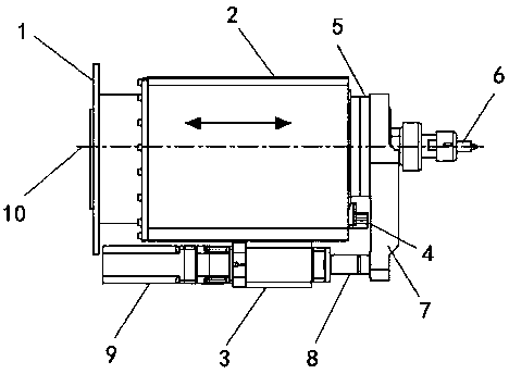
[0016] figure 1 They are a friction stir welding device according to an embodiment of the present invention. The friction stir welding device includes a flange seat 1 for connecting third-party equipment, a main box 2 connected to the flange seat 1, and a ball screw pair. 3. The guide rail slider 4 and the electric spindle 5 arranged on the main machine box 2, the stirring tool 6 bolted on the electric spindle 5, the limit plate 7 which is relatively static with the electric spindle 5, and the constant pressure The sensor 8, the A-axis connected with the ball screw pair 3 drives the servo motor 9, the guide rail slider 4 serves as the sliding support of the electric spindle 5 along the A-axis, wherein the constant pressure sensor 8 is used to obtain the When the shaft shoulder end surface of the stirring tool 6 touches the surface of the part to be welded, that is, when the stirring tool 6 is idling to plunge into the real-time pressure feedback value of the part to be welded,...


PUM


Abstract

The invention provides a friction-stir welding device. The friction-stir welding device comprises a flange base, a main machine box, a ball screw pair, a guide rail sliding block, an electric spindle,a stirring tool, a limiting plate, a constant pressure sensor and an A-axis driving servo motor. The flange base is used for connecting third-party equipment. The main machine box and the ball screwpair are connected with the flange base. The guide rail sliding block and the electric spindle are arranged on the main machine box. The stirring tool is connected to the electric spindle in a boltingmanner. The limiting plate and the constant pressure sensor keep the static state relative to the electric spindle. The A-axis driving servo motor is connected with the ball screw pair. The guide rail sliding block serves as a sliding support for the electric spindle along the A axis. The constant pressure sensor is used for acquiring the real-time pressure feedback numerical value when a shaft shoulder end face of the stirring tool makes contact with the surface of a part to be welded. The A-axis driving servo motor receives the real-time pressure feedback numerical value and controls the A-axis press-in regulating quantity of the stirring tool according to the real-time pressure feedback numerical value. The friction-stir welding device is easy and convenient to operate, can achieve welding of more types of light alloy more flexibly in a wider range, and is stable in operation and convenient to move.

Description

technical field [0001] The invention belongs to the field of friction stir welding equipment, and is mainly used for connecting a robot or connecting with other equipment to realize friction stir welding. Background technique [0002] The friction stir welding method is the same as conventional friction welding. Friction stir welding also uses friction heat and plastic deformation heat as welding heat source. The difference is that the welding process of friction stir welding is that a cylinder or other shape (such as a threaded cylinder) of the welding pin (welding pin) is inserted into the joint of the workpiece, and through the high-speed rotation of the welding head, it is connected with the welding pin. The workpiece material rubs against each other, which increases the temperature of the material at the joint and softens it. At the same time, the material is subjected to friction stir to complete the welding. During the welding process, the workpiece should be rigid...

Claims


Application Information

Patent Timeline
Patent Type & Authority Applications(China)
IPC IPC(8): B23K20/12
CPCB23K20/1245
Inventor 姚君山吕将朱玉宁
Owner JIANGSU ASWEMET PRECISION TECH CO LTD
Why Eureka
Try Eureka