Multifunctional automatic capping machine

A capping machine and multi-functional technology, which is applied to flange-type bottle caps, conveyor objects, bottle/container caps, etc. Guaranteed accuracy and flatness, reasonable structural design, and high operating efficiency

Pending Publication Date: 2018-09-14
山东天振药业有限公司
View PDF0 Cites 3 Cited by
  • Summary
  • Abstract
  • Description
  • Claims
  • Application Information

AI Technical Summary

Problems solved by technology

[0002] In the process of preparing medicines in glass bottles, the capping process needs to be completed after sub-packaging. At present, manual and mechanical methods are usually used for capping, and the glass bottles containing medicines are transported to the One side of the capping tool is transported to wait for the subsequent capping. During the process of conveying the glass, it is usually necessary to manually hold the bottle caps and then place them on each bottle on the conveyor belt in turn, which leads to low operating efficiency and low accuracy during placement. low, it is easy to have the problem of leaking the bottle cap on the bottle body or placing the bottle cap in an inappropriate position; at the same time, by manually placing the bottle cap, when the amount of medicine bottles that need to be crimped is large, it takes a lot of manpower, Material resources, considering the reaction time of the operator when placing the bottle caps manually, the speed of the conveying surface cannot be too fast, so that it is difficult to improve the overall capping efficiency as a whole. Obviously, the existing capping machines cannot be more effective. satisfy people's demands

Method used


Image

  • Multifunctional automatic capping machine
  • Multifunctional automatic capping machine
  • Multifunctional automatic capping machine

Examples


Embodiment Construction

[0031] In order to clearly illustrate the technical features of this solution, the present invention will be described in detail below through specific implementation modes and in conjunction with the accompanying drawings.

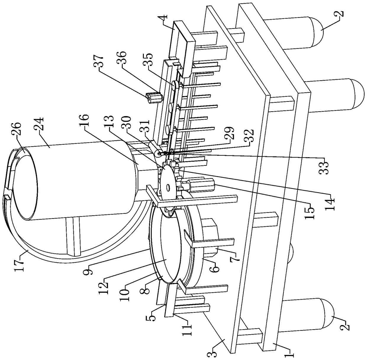
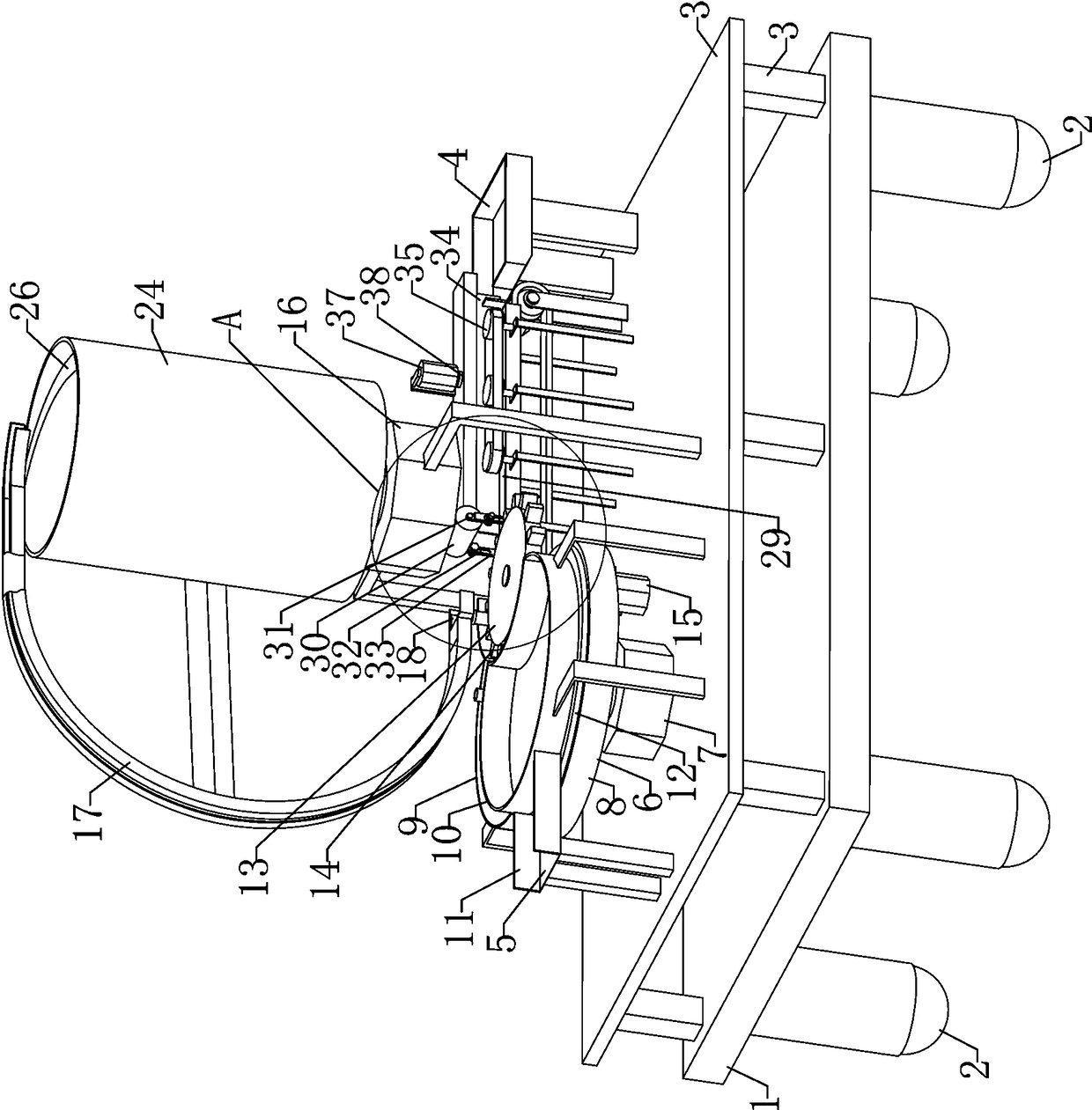
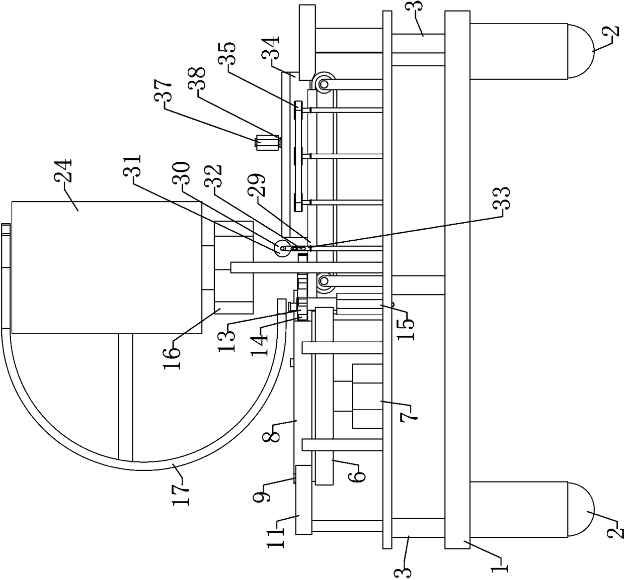
[0032] Such as Figure 1-9 As shown in the figure, the multi-functional automatic capping machine includes a base 1, and a wheel 2 with self-locking function is provided at the bottom of the base 1, which can easily shift the entire device and adapt to work in different positions. A frame body 3 is arranged on the seat 1, a bottle body conveying device is provided on the top platform of the frame body 3, a capping device is arranged at the end of the bottle body conveying device, and a bottle body conveying device on the side close to the capping device A bottle cap conveying device is provided above the capping device, and a medicine bottle exporting collection platform 4 is provided on the rear side of the capping device; through the bottle body conveyi...


PUM


Abstract

The invention relates to the field of drug subpackage capping equipment, in particular to a multifunctional automatic capping machine. The multifunctional automatic capping machine comprises a base. Wheels with a self-locking function are arranged at the bottom of the base, and a frame body is arranged on the base. A bottle conveying device is arranged on a top platform of the frame body, and a capping device is arranged at the tail end of bottle conveying device. A bottle cap conveying device is arranged on the position, close to one side of the capping device, of the upper portion of the bottle conveying device, and a drug bottle leading-out collection table is arranged on the rear side of the capping device. The multifunctional automatic capping machine is reasonable in structural design, the steps such as full-automatic conveying of bottles and bottle caps, sleeving connection of the bottles and the bottle caps and capping can be achieved, the operation efficiency and accurate rateare high, accordingly, the multifunctional automatic capping machine can adapt to the working environment with the large yield, and the requirements for mass production and automatic capping can be effectively met.

Description

technical field [0001] The invention relates to the field of medicine subpackaging and capping equipment, in particular to a multifunctional automatic capping machine. Background technique [0002] In the process of preparing medicines in glass bottles, the capping process needs to be completed after sub-packaging. At present, manual and mechanical methods are usually used for capping, and the glass bottles containing medicines are transported to the One side of the capping tool is transported to wait for the subsequent capping. During the process of conveying the glass, it is usually necessary to manually hold the bottle caps and then place them on each bottle on the conveyor belt in turn, which leads to low operating efficiency and low accuracy during placement. low, it is easy to have the problem of leaking the bottle cap on the bottle body or placing the bottle cap in an inappropriate position; at the same time, by manually placing the bottle cap, when the amount of medi...

Claims


Application Information

Patent Timeline
Patent Type & Authority Applications(China)
IPC IPC(8): B67B3/10B67B3/064B65G47/14B65G47/84B65G47/248
CPCB67B3/10B65G47/1428B65G47/248B65G47/84B67B3/064
Inventor 田文岩李攀陈兴利陈超潘龙曹贤李会刚闫春芹冯亚星
Owner 山东天振药业有限公司
Why Eureka
Try Eureka