Scroll-type compressor with variable displacement mechanism

A variable capacity compressor, scroll type technology, applied in the direction of liquid variable capacity machines, rotary piston machines, mechanical equipment, etc., can solve the problems of increasing the axial size and weight of the compressor

Inactive Publication Date: 2002-05-22
SANDEN CORP
View PDF2 Cites 0 Cited by
  • Summary
  • Abstract
  • Description
  • Claims
  • Application Information

AI Technical Summary

Problems solved by technology

Moreover, if the thickness of the end plate 501 is increased in order to provide a cylinder ...

Method used


Image

  • Scroll-type compressor with variable displacement mechanism
  • Scroll-type compressor with variable displacement mechanism
  • Scroll-type compressor with variable displacement mechanism

Examples


Embodiment Construction

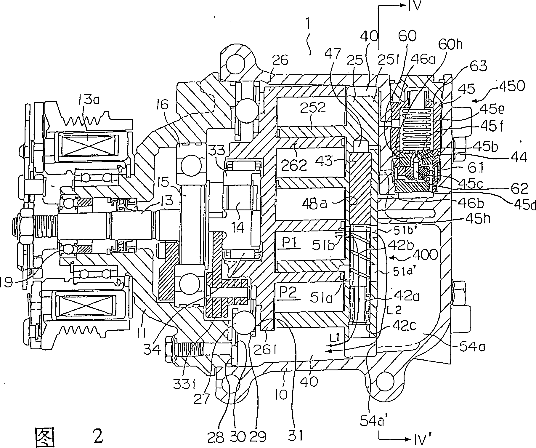
[0028] A first embodiment of the present invention will now be described with reference to FIGS. 2-4. As shown in FIG. 2, the scroll compressor 1 has a housing 10 and a front plate 11 connected thereto. In the casing 10, a fixed scroll 25 is fixedly placed, and an orbiting scroll 26 is provided.

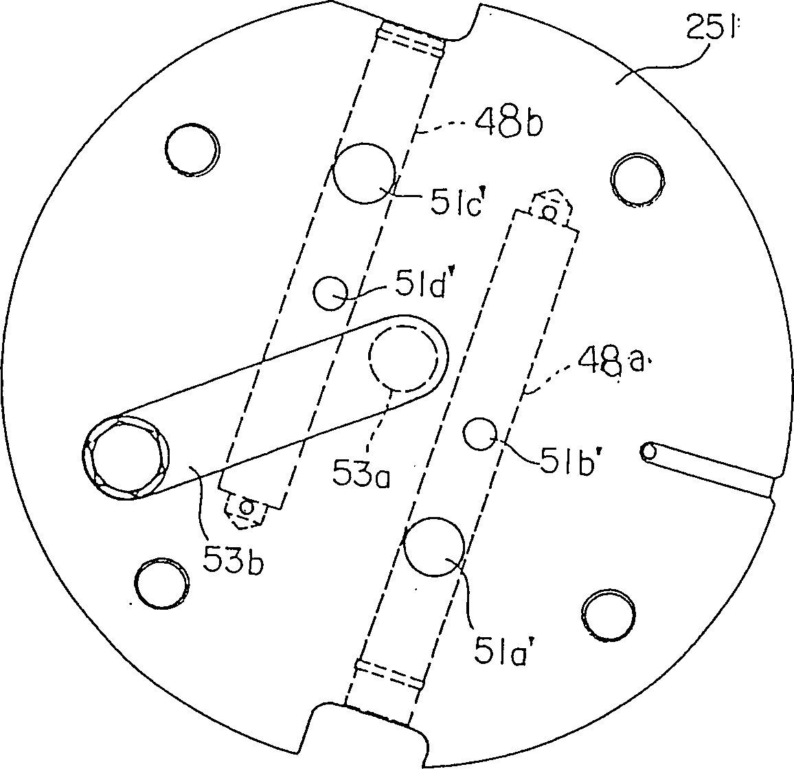
[0029] The fixed scroll 25 includes a disk-shaped fixed end plate 251, and a fixed screw 252 integrally formed therewith and protruding from the fixed end plate 251. As shown in FIG. Similarly, the orbiting scroll 26 includes a disk-shaped orbiting end plate 261 , and an orbiting screw 262 integrally formed therewith and protruding from the orbiting end plate 261 . Since the spiral members 252 and 262 are opposed to each other, compression pockets P1, P2 are formed between the fixed scroll member 25 and the orbiting scroll member 26 .

[0030] On the front plate 11, a drive shaft 13 is rotatably supported by radial bearings 16 and 19. As shown in FIG. An eccentric rod 14 axially p...


PUM


Abstract

A variable scroll compressor used in vehicle air-conditioning system has a cylinder formed at the terminal plate of a fixed cyclone element and a low-pressure chamber arranged at the rear end of the compressor. A plurality of through holes vertically pass through the cylinder from a plurality of pressure chambers and low-pressure chambers that are enclosed by the fixed cyclone element and a revolution cyclone element, and cooling air can return to control the capacity of the compressor. As a return channel that passes through the low-pressure chamber is arranged besides the regular return channel that passes through the cylinder, feedback pressure loss accompanying the cooling air and the minimum capacity of the compressor can be reduced effectively.

Description

technical field [0001] The invention relates to a scroll compressor with a variable volume device. More precisely, it relates to a scroll compressor with a variable displacement device having an improved minimum capacity. Background technique [0002] Generally, in the field of compressors, a method for returning part of the refrigerant gas in the compression chamber to the suction chamber is known. Fig. 1 is a longitudinal sectional view of a prior art conventional compressor according to Japanese Patent Publication Hei5-280476. In FIG. 1, the capacity control device 600 includes: a hollow cylinder 510 located in the end plate 501 of the fixed scroll 500; several through holes 530 communicating the compression chambers 520a, 520b with the cylinder 510; Plunger piston 540 of bore 530; a means for adjusting the position of the plunger piston 540 along the cylinder 510 axis. The outermost one of the through holes 530 communicates the cylinder 510 and the suction chamber 550...

Claims


Application Information

Patent Timeline
IPC IPC(8): F04C18/02F04B49/00F04C28/12
CPCF04C28/12
Inventor 东山彰良
Owner SANDEN CORP
Why Eureka
Try Eureka