Internal combustion engine with exhaust device

A technology for exhaust equipment and internal combustion engines, applied to internal combustion piston engines, exhaust treatment, mechanical equipment, etc., can solve problems such as shortened service life of components, damage to catalytic converters, damage to gasoline particulate filters, etc., to reduce emissions and reduce efficiency Effect

Active Publication Date: 2018-09-14
BAYERISCHE MOTOREN WERKE AG
View PDF10 Cites 1 Cited by
  • Summary
  • Abstract
  • Description
  • Claims
  • Application Information

AI Technical Summary

Problems solved by technology

These existing arrangements have the disadvantage that a high heat release can lead to damage to the gasoline particulate filter or to the catalytic converter or shorten the service life of emission-related components

Method used


Image

  • Internal combustion engine with exhaust device
  • Internal combustion engine with exhaust device
  • Internal combustion engine with exhaust device

Examples


Embodiment Construction

[0027] then in Figures 1 to 13 In , the same reference numerals are applied to the same components.

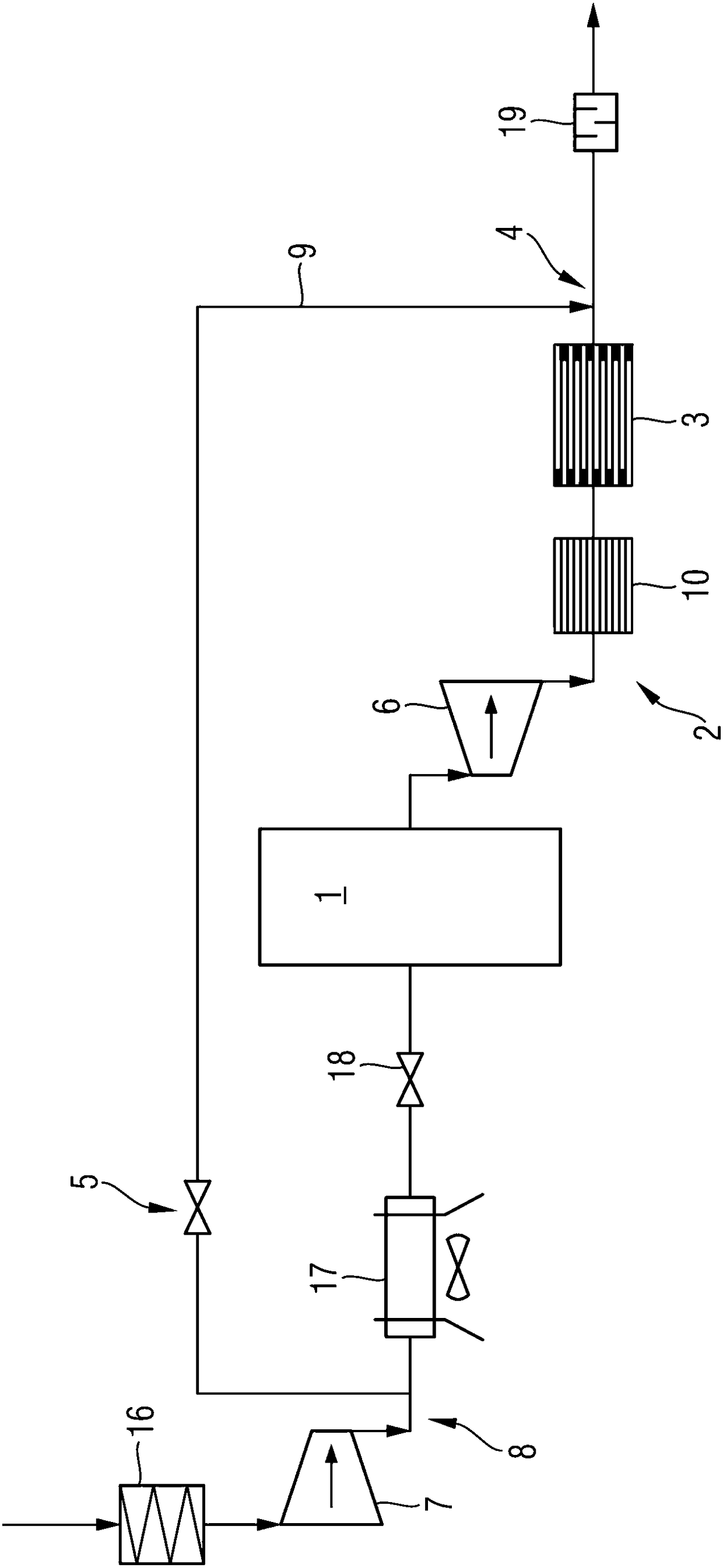
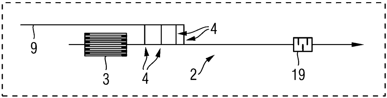
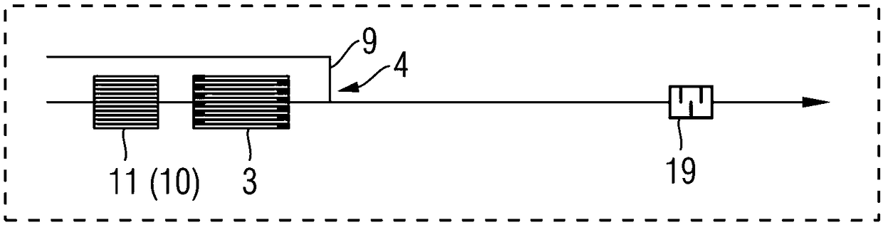
[0028] figure 1 A schematic design of an internal combustion engine 1 with an exhaust gas system 2 according to the invention is shown. The exhaust system 2 serves to discharge the exhaust gas of the internal combustion engine 1 , wherein a particle filter 3 is arranged in the exhaust system 2 . Furthermore, a secondary air inlet 4 is provided in the exhaust device 2 , which introduces secondary air into the exhaust device 2 via a closing element 5 . The closure element 5 can be, for example, a valve or a damper. According to the invention, the secondary air inlet 4 is arranged downstream of the particle filter 3 in the flow direction of the exhaust gas in the exhaust system 2 .

[0029] The flow direction of the exhaust gas is not indicated by arrows in the exhaust system 2 . The flow direction of the secondary air is likewise not indicated by arrows in the region of t...


PUM


Abstract

The invention relates to an internal combustion engine with an exhaust device used for discharging exhaust gas in an internal combustion engine. A particle filter is arranged in the exhaust device, the exhaust device is also provided with a secondary air inlet used for introducing secondary air to the exhaust device through an enclosed element, and the secondary air inlet is arranged at the downstream of the particle filter along the flowing direction of the exhaust gas in the exhaust device. According to the structure of the internal combustion engine, the particle filter can be free from thedamage of high heat release and reduce emission of carbon monoxide.

Description

technical field [0001] The invention relates to an internal combustion engine with an exhaust system having the features of the preamble of claim 1 . Background technique [0002] For the technical field see, for example, German laid-open document DE 10 2012 021 573 A1. A method for operating a burner and an exhaust system with a burner that can be operated in this way are known from this publication. A method is described for operating a burner of an exhaust system which is operated with air and fuel, combining the burner exhaust gas of the burner with the exhaust gas of an internal combustion engine in an externally ignited internal combustion engine and mixing the thus obtained The exhaust gas is fed to at least one exhaust gas catalytic converter with three-way catalytic function, wherein the actual oxygen content (λ-actual) of the mixed exhaust gas or a variable related thereto is measured and the fuel quantity (m k ), so that the actual oxygen content (λ-actual) at l...

Claims


Application Information

Patent Timeline
Patent Type & Authority Applications(China)
IPC IPC(8): F01N3/30F01N13/00F01N3/035
CPCF01N3/035F01N3/30F01N13/00F01N2230/02F01N2230/04F01N2570/10F01N2570/14F01N13/009F01N1/14F01N3/021F01N3/05F01N3/2006F01N3/025Y02T10/12
Inventor N·彼得斯
Owner BAYERISCHE MOTOREN WERKE AG
Why Eureka
Try Eureka