Adjusting mechanism for inlet guide blades of centrifugal blower

A centrifugal blower and regulating mechanism technology, applied in the direction of machines/engines, mechanical equipment, liquid fuel engines, etc., can solve problems such as noise pollution, reduce the aerodynamic performance of the whole machine, weaken the flow separation at the inlet guide vane, and achieve weakened flow separation , Reduce aerodynamic loss and reduce energy consumption

Pending Publication Date: 2018-09-14
安徽虎渡科达流体机械有限公司
View PDF9 Cites 6 Cited by
  • Summary
  • Abstract
  • Description
  • Claims
  • Application Information

AI Technical Summary

Problems solved by technology

[0002] The high-speed centrifugal blower adjusts the flow direction and flow rate of the airflow by adjusting the angle of the inlet guide vane. The fluid produces aerodynamic loss, which reduces the aerodynamic performance of the whole machine, and noise pollution is caused by the excessive separation of the blade surface, so it is necessary to weaken the flow separation at the inlet guide vane and improve the efficiency of the centrifugal blower
The existing practice is to change the plate guide vane to an airfoil guide vane, but changing to an airfoil guide vane does not improve the aerodynamic performance much, especially for the centrifugal blower with an S-shaped inlet channel, which reduces the aerodynamic loss at the guide vane not obvious

Method used


Image

  • Adjusting mechanism for inlet guide blades of centrifugal blower
  • Adjusting mechanism for inlet guide blades of centrifugal blower
  • Adjusting mechanism for inlet guide blades of centrifugal blower

Examples


Embodiment Construction

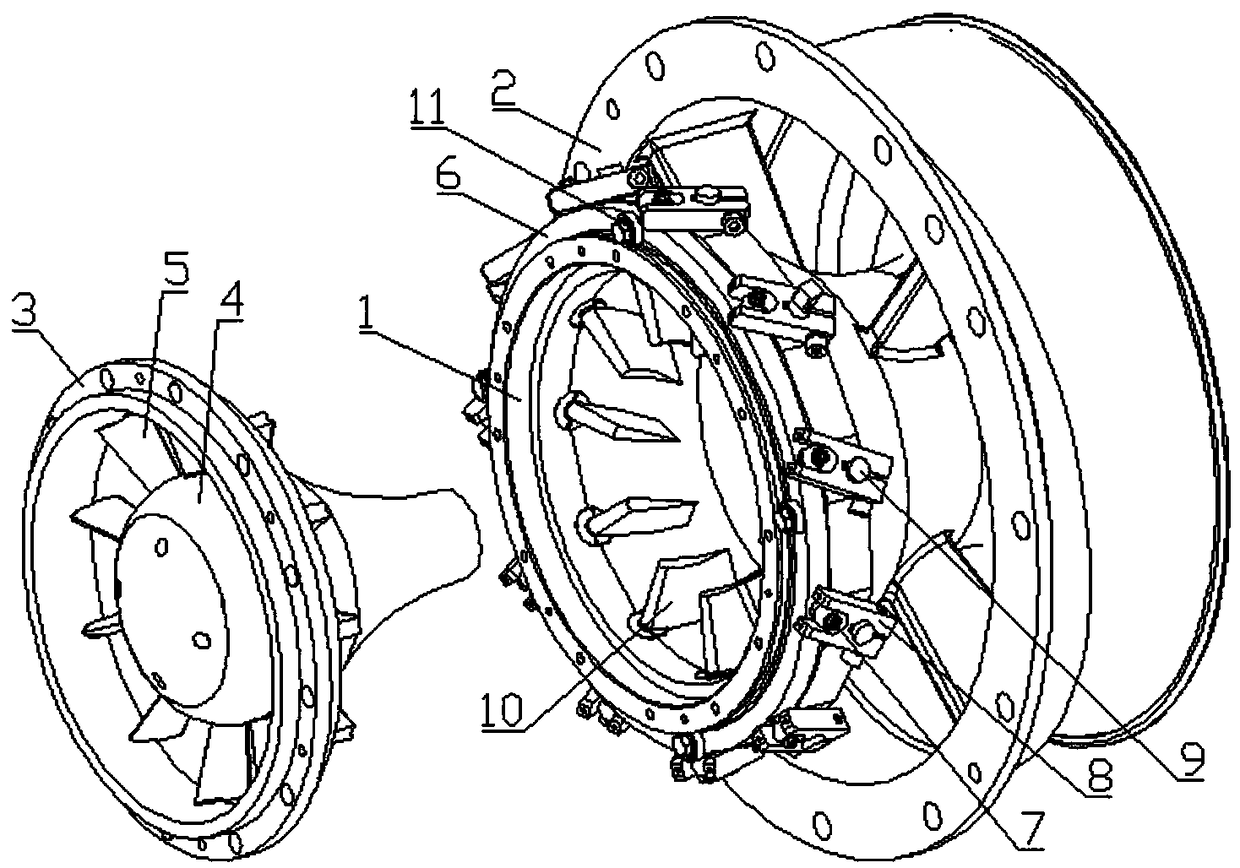
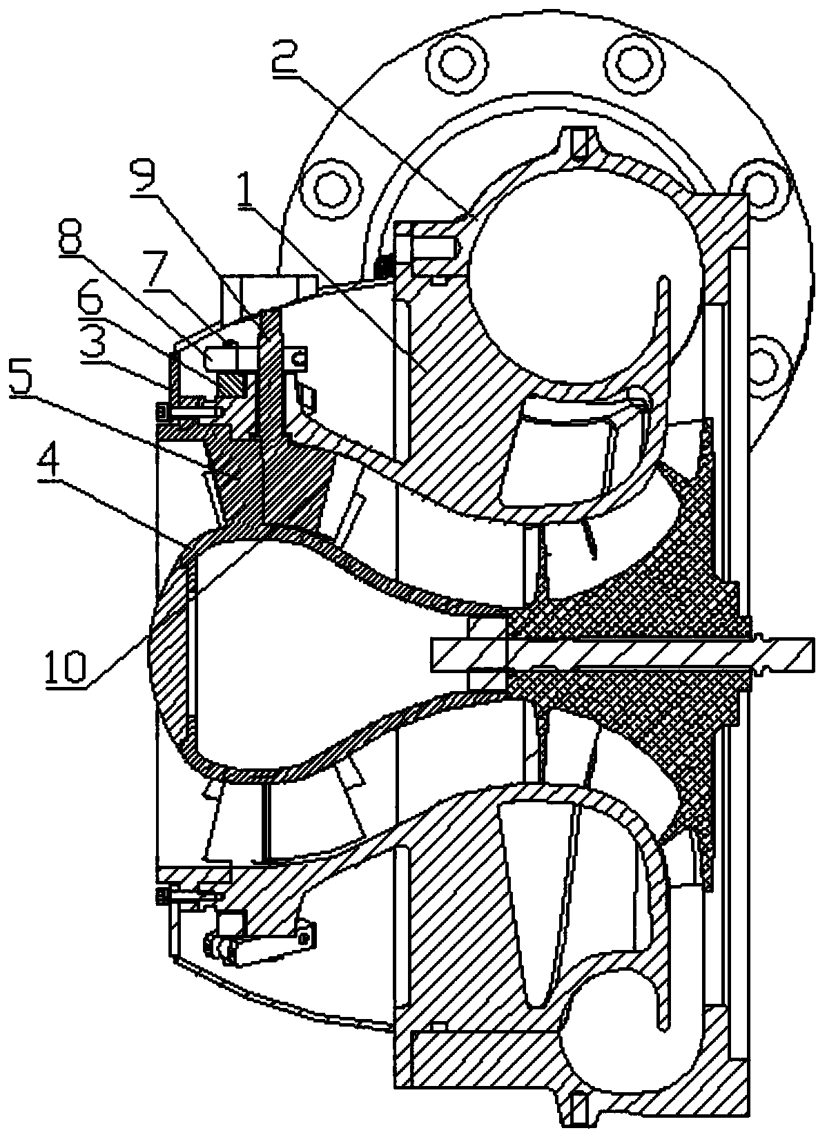
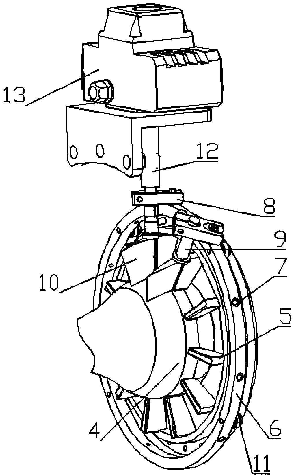
[0017] Below in conjunction with accompanying drawing, the present invention will be further described in detail, so that those skilled in the art can understand more clearly, as figure 1 , figure 2 , image 3 , Figure 4 As shown, the present invention includes:

[0018] Inner volute 1, outer volute 2, cover cap 3, front guide vane assembly and rear guide vane assembly,

[0019] The front-section guide vane assembly includes a flow guide 4, a number of front-section guide vanes 5 are evenly and fixedly connected to the outer peripheral wall of the flow guide 4 along the circumferential direction, and the upper end of the front-section guide vanes 5 is fixedly connected to the peripheral wall of the inner volute 1 ;

[0020] The rear guide vane assembly includes a centrally rotatable drive ring 6 set on the outer peripheral surface of the inner volute 1, and the drive ring pins 7 having the same number as the front guide vanes are evenly distributed on the outer periphera...


PUM


Abstract

The invention discloses an adjusting mechanism for inlet guide blades of a centrifugal blower. The adjusting mechanism comprises an inner volute, an outer volute, a shield cap, a front-section guide blade assembly and a rear-section guide blade assembly. During working, an actuator drives one of rear-section guide blade rotating shafts to rotate through a coupling, the rear-section guide blade rotating shaft rotates to drive a driving ring to rotate, accordingly, all the guide blade rotating shafts are driven to rotate, and the purpose of adjusting the rotating angle of the rear-section guideblades is achieved. According to the adjusting mechanism for the inlet guide blades of the centrifugal blower, a traditional single-blade flow guiding mode is broken through, by adopting the mode thatthe front-section guide blades are fixed and the rear-section guide blades rotate, adjusting of the tandem-cascade-type guide blades is achieved, and flowing separation of an air flow at the guide blades is weakened; and under the situation of ensuring adjustability of the flow direction and the flow amount of the air flow, the aerodynamic loss brought by the guide blades is reduced, the efficiency of the whole mechanism is improved, and energy consumption is reduced.

Description

technical field [0001] The invention belongs to the technical field of blowers, and in particular relates to an adjustment mechanism for inlet guide vanes of a centrifugal blower. Background technique [0002] The high-speed centrifugal blower adjusts the flow direction and flow rate of the airflow by adjusting the angle of the inlet guide vane. The fluid produces aerodynamic loss, which reduces the aerodynamic performance of the whole machine, and noise pollution is caused by the excessive separation of the blade surface. Therefore, it is necessary to weaken the flow separation at the inlet guide vane and improve the efficiency of the centrifugal blower. The existing practice is to change the plate guide vane to an airfoil guide vane, but changing to an airfoil guide vane does not improve the aerodynamic performance much, especially for the centrifugal blower with an S-shaped inlet channel, which reduces the aerodynamic loss at the guide vane Not obvious. Contents of the...

Claims


Application Information

Patent Timeline
Patent Type & Authority Applications(China)
IPC IPC(8): F04D29/46F04D29/00F04D25/08
CPCF04D25/08F04D29/002F04D29/462
Inventor 倪奇峰郝飞龚一方
Owner 安徽虎渡科达流体机械有限公司
Why Eureka
Try Eureka