Fan device having self-cleaning function

A function and fan technology, applied in the field of fan devices with self-cleaning function, can solve the problems of low exhaust flow efficiency, increased motor energy consumption, unsatisfactory, etc., and achieve easy structure, simple structure, and cleaning ability strong effect

Active Publication Date: 2018-09-14
彭志军
View PDF7 Cites 9 Cited by
  • Summary
  • Abstract
  • Description
  • Claims
  • Application Information

AI Technical Summary

Problems solved by technology

Although this cleaning method can clean the impeller to a certain extent, reduce the erosion of the impeller by grease and dust, and improve the pumping and exhaust flow efficiency of the impeller, it also has relatively large deficiencies, mainly reflected in these Aspects: (1) It is necessary to design a nozzle head with a complex structure to reach the inside of the impeller, so as to clean the inside of the impeller without affecting the rotation space of the impeller, which is difficult to process and assemble; (2) The nozzle head The cleaning and coverage of the impeller cannot achieve 100% absolute coverage, such as the corners of the impeller, the inner and outer end faces, so that the cleaning of the impeller can only be partially cleaned, and it cannot be fully cleaned; when the impeller is used for a long time, the same There are problems of low extraction and exhaust flow efficiency and increased energy consumption of the motor
It can only achieve a slightly better effect than the fan without cleaning function, and cannot achieve a more ideal working state
(3) The spray head only cleans the impeller, ignoring the cleaning of the inner wall of the volute that accommodates the impeller; because in practice, the inner wall of the fan volute has a lot of grease and dust; and the inner wall of the volute Too much grease and dust in the air will greatly affect the airflow efficiency, which in turn will increase the power consumption of the motor and reduce the exhaust capacity of the fan.
However, in the technical solution disclosed in CN106311669A, because the water at the bottom of the volute can only soak into the bottom edge of the wind wheel, even if the wind wheel rotates slowly while cleaning, it can only clean the part of the wind wheel. It is impossible to completely clean the inner wall of the wind wheel and the volute; moreover, it uses the method of rotating the wind wheel at a slow speed while cleaning, so that the number and frequency of the wind wheel being impacted by ultrasonic bubbles are greatly reduced
Therefore, the technical scheme of CN106311669A is very unsatisfactory in terms of cleaning effect, and is unsatisfactory

Method used


Image

  • Fan device having self-cleaning function
  • Fan device having self-cleaning function
  • Fan device having self-cleaning function

Examples


Embodiment 1

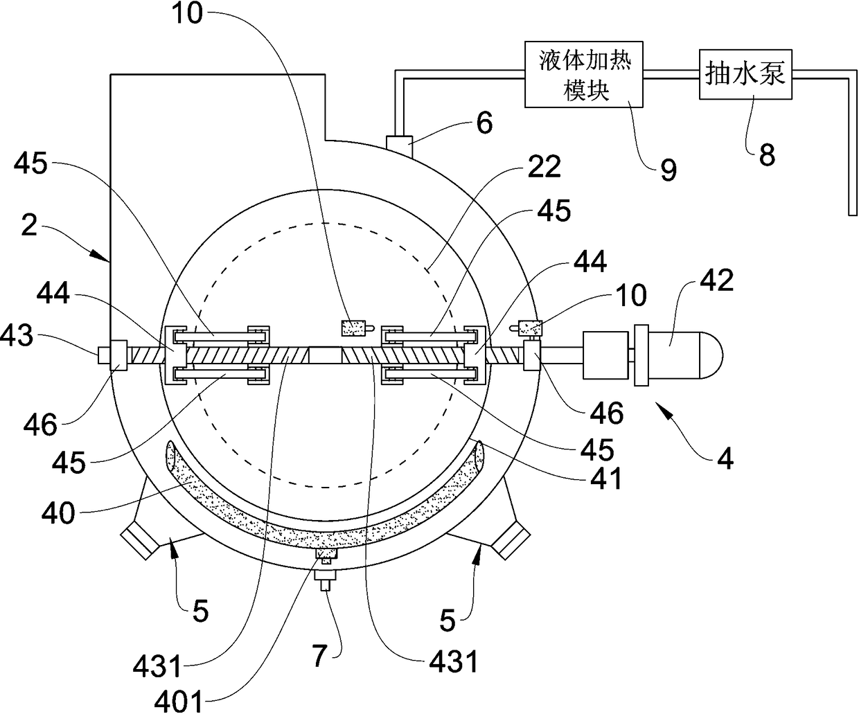
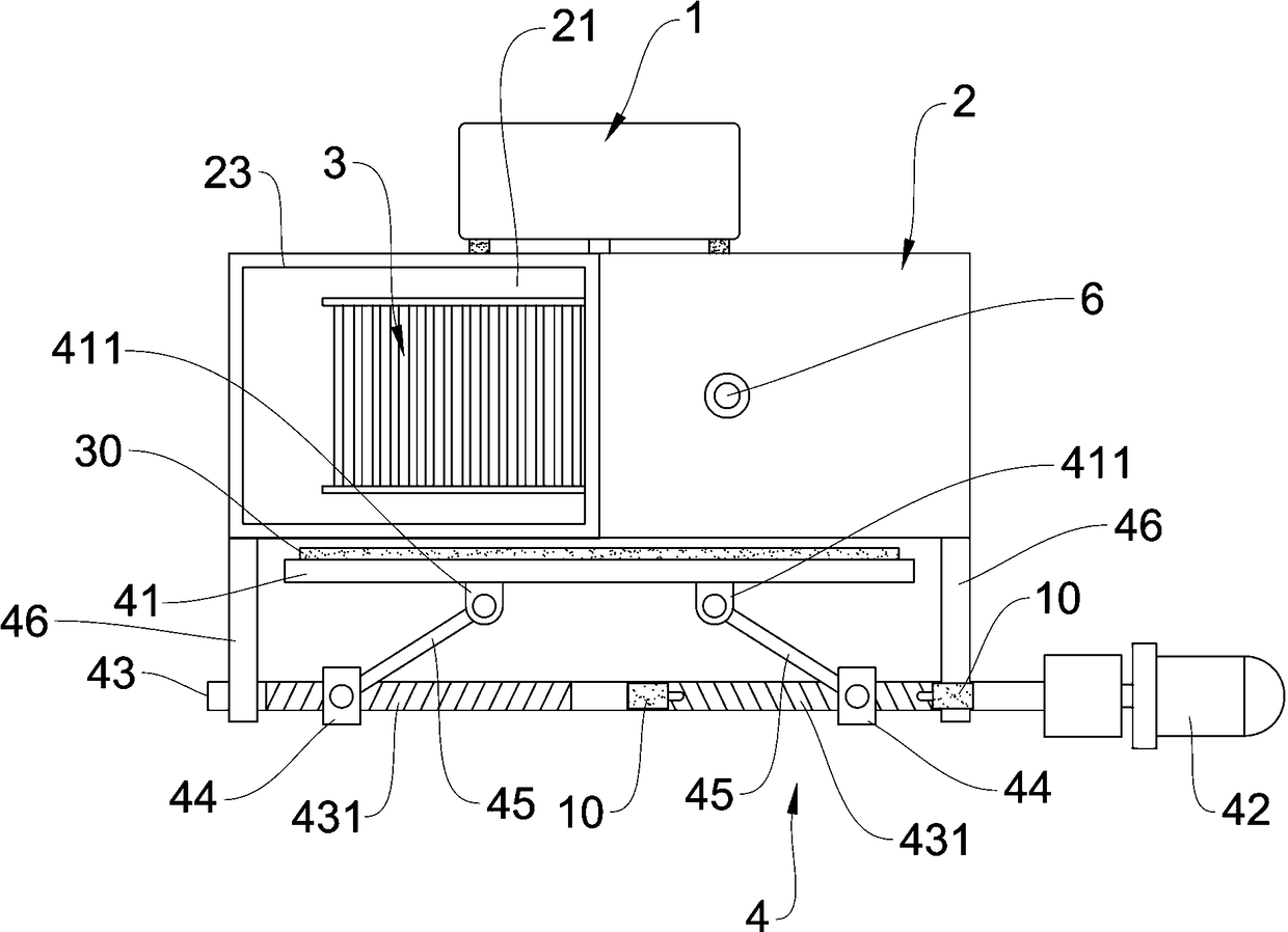
[0015] like figure 1 , figure 2 As shown, a fan device with a self-cleaning function according to the present invention includes an impeller motor 1, a fan casing 2, and an impeller 3. The fan casing 2 is provided with a closed chamber 21 for accommodating the impeller 3. , the fan casing 2 is also provided with an air inlet 22 and an air outlet 23 respectively; the impeller motor 1 is arranged outside the fan casing 2, and the motor shaft of the impeller motor 1 extends into the closed chamber 21; so The impeller 3 is arranged in the closed chamber 21 of the fan casing 2 and is connected with the motor shaft of the impeller motor 1 . In order to realize the self-cleaning function of the fan proposed by the present invention, the present invention also includes a capping mechanism 4 and an ultrasonic transducer 5,

[0016] another example figure 1 and figure 2 As shown, the capping mechanism 4 further includes a cap plate 41, a capping motor 42, a screw 43, a nut member ...

Embodiment 2

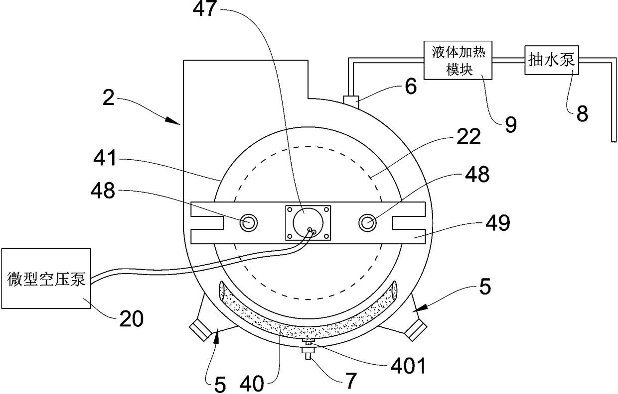
[0024] The difference between this embodiment 2 and the previous embodiment 1 lies in the structure of the capping mechanism 4. The capping mechanism 4 in the first embodiment uses a motor to push the opening and closing of the cover plate 41, while this embodiment The second is to use an air cylinder to push the opening and closing of the cover plate 41 . Except for the structure of the push cover 41 being different, the purpose and principle process to be implemented in the second embodiment are basically the same as those in the first embodiment. Therefore, in the second embodiment, the same parts as those in the first embodiment will not be repeated. The specific scheme of the second embodiment is as follows: image 3 and Figure 4 As shown, a fan device with a self-cleaning function includes an impeller motor 1, a fan casing 2, and an impeller 3. The fan casing 2 is provided with a closed chamber 21 for accommodating the impeller 3. 2 is also provided with an air inlet...


PUM


Abstract

The invention relates to a fan device having a self-cleaning function. The fan device comprises a vane wheel motor, a fan housing, a vane wheel, a seal cover mechanism and ultrasonic transducers, wherein the seal cover mechanism also comprises a cover plate, a seal cover motor, a screw rod, nut pieces and push-pull rods; the screw rod is erected in front of an air inlet; the nut pieces are mountedon the screw rod; one ends of the push-pull rods are hinged to the nut pieces, and the other ends of the push-pull rods are hinged to the outer side surface of the cover plate; the seal cover motor is integrally in transmission connection with one end of the screw rod to drive the screw rod to rotate, so that the purpose that the nut pieces are in axial motion back and forth along the screw rod is realized, the cover plate is blocked at the air inlet in a sealing manner, or the cover plate is away from the air inlet; a sealing ring is also arranged on the inner side surface of the cover plate; the ultrasonic transducers are arranged on the outer wall of the bottom of the fan housing; a water inlet port is also formed in the fan housing; and a draining hole is also formed in the bottom ofthe fan housing. Through adoption of the fan device disclosed by the invention, thorough no-dead cleaning on the vane wheel and the inner wall of the fan housing can be realized, the cleaning capacityis high, and the cleaning effect is good.

Description

technical field [0001] The invention relates to a fan or the field related to a fan mechanism, in particular to a fan device. Background technique [0002] Fan devices are widely used in cooling, ventilation, and oil fume extraction in household appliances, ventilation, dust removal, cooling and air conditioning in factories, mines, tunnels, cooling towers, vehicles, aircraft, ships and buildings, boilers and industrial furnaces kiln ventilation and induced draft, etc. However, in the application of fan devices in various fields, there is a serious problem, that is, the impeller of the fan is very easy to stick to dust, grease, etc., and with the prolongation of use time, dust, grease, etc. adhere to the entire impeller and impeller working. The inner cavity wall, which greatly affects the efficiency of the exhaust air flow of the fan, increases the power consumption of the motor, and shortens the service life of the motor. [0003] In order to solve these problems, in som...

Claims


Application Information

Patent Timeline
Patent Type & Authority Applications(China)
IPC IPC(8): F04D29/70F04D29/42B08B3/12
CPCF04D29/4213F04D29/4226F04D29/703F04D29/705B08B3/12F04D29/701
Inventor 彭志军
Owner 彭志军
Why Eureka
Try Eureka