Alloy steel fastener cooling equipment

A technology for cooling equipment and fasteners, which is applied in the field of cooling equipment for alloy steel fasteners, can solve problems such as uneven cooling of fasteners, reduce work efficiency, and increase work difficulty, so as to reduce the difficulty of taking parts and increase Production efficiency and the effect of increasing production volume

Inactive Publication Date: 2018-09-14
扬州市金诺尔不锈钢有限公司
View PDF0 Cites 0 Cited by
  • Summary
  • Abstract
  • Description
  • Claims
  • Application Information

AI Technical Summary

Problems solved by technology

[0002] With the continuous advancement of science and technology in different fields, more and more undeveloped fields need people or equipment to enter. For these special environments, the performance requirements of equipment parts are extremely high. The main purpose of alloy steel fasteners is to connect Various components play a very important role in the connection of equipment, so their performance and strength have a very, very large impact on the service life of the equipment. Alloy steel fasteners need to be cooled during production. Traditional alloy steel cooling equipment, directly put the fasteners into the cooling pool for cooling, and take out the fasteners after cooling. If it is not timely, the interference of external forces will also cause deformation of the fasteners, which will reduce the qualified rate and cause waste of resources, and the size of the cooling pool is limited, and there are also a number of stored fasteners, so it is necessary to take out the fastening Fasteners can only be added to the fasteners, which reduces work efficiency. At the same time, the operation of picking up parts is troublesome and time-consuming, which increases the difficulty of work. In addition, a large amount of coolant is often injected into the cooling pool, resulting in a waste of resources.

Method used


Image

  • Alloy steel fastener cooling equipment
  • Alloy steel fastener cooling equipment
  • Alloy steel fastener cooling equipment

Examples


Embodiment Construction

[0017] The following will clearly and completely describe the technical solutions in the embodiments of the present invention with reference to the accompanying drawings in the embodiments of the present invention. Obviously, the described embodiments are only some, not all, embodiments of the present invention. Based on the embodiments of the present invention, all other embodiments obtained by persons of ordinary skill in the art without making creative efforts belong to the protection scope of the present invention.

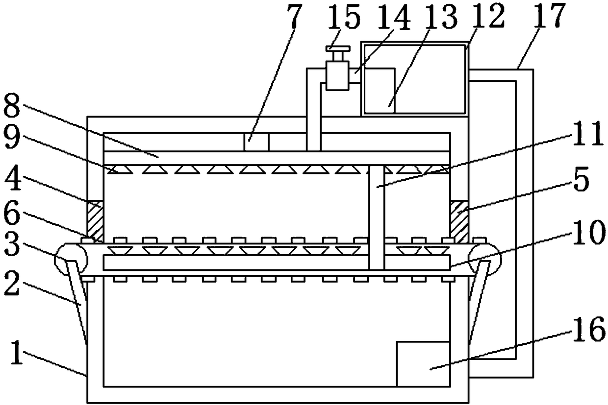
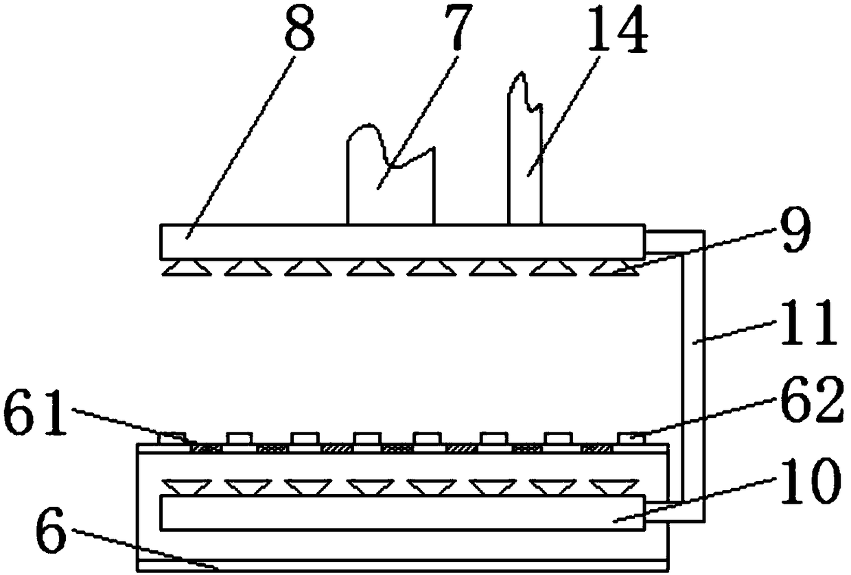
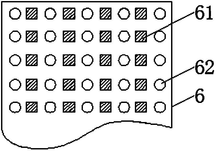
[0018] see Figure 1-3 , the present invention provides a technical solution: a cooling device for alloy steel fasteners, including a cooling box 1, the outer walls of the left and right sides of the cooling box 1 are provided with support rods 2, and the rear rotating shaft of the support rod 2 is provided with a rotating roller 3, The two groups of rotating rollers 3 are driven by the conveyor belt 6, and the conveyor belt 6 is a mesh conveyor belt, which is...


PUM


Abstract

The invention belongs to the technical field of alloy steel fastener cooling and discloses alloy steel fastener cooling equipment. The alloy steel fastener cooling equipment comprises a cooling box. Two sets of rotating rollers conduct transmission through a conveying belt. A feeding inlet and a discharging outlet are formed in the outer walls of the left side and the right side of the cooling boxcorrespondingly. Spraying heads are evenly arranged at the bottom of an upper mounting plate and the top of a lower mounting plate. A cooling liquid storage tank is arranged on the right side of thetop of the cooling box. The left side of a hose extends to an inner cavity of the cooling box and is connected with the right side of the top of the upper mounting plate. A return pipe is arranged onthe outer wall of the right side of the cooling liquid storage tank, and the right side of the return pipe extends to the right side of the bottom of the inner cavity of the cooling box and is connected with a liquid pump. In the alloy steel fastener cooling equipment, fasters are conveyed through the conveying belt, the situation that the fasteners are accumulated together and consequently are cooled non-uniformly is well avoided, the number of the damaged fasteners due to nonuniform cooling is decreased; and meanwhile through the spraying heads on the upper mounting plate and the lower mounting plate, cooling is more uniform, and the production efficiency is improved.

Description

technical field [0001] The invention relates to the technical field of cooling alloy steel fasteners, in particular to cooling equipment for alloy steel fasteners. Background technique [0002] With the continuous advancement of science and technology in different fields, more and more undeveloped fields need people or equipment to enter. For these special environments, the performance requirements of equipment parts are extremely high. The main purpose of alloy steel fasteners is to connect Various components play a very important role in the connection of equipment, so their performance and strength have a very, very large impact on the service life of the equipment. Alloy steel fasteners need to be cooled during production. Traditional alloy steel cooling equipment, directly put the fasteners into the cooling pool for cooling, and take out the fasteners after cooling. If it is not timely, the interference of external forces will also cause deformation of the fasteners, w...

Claims


Application Information

Patent Timeline
Patent Type & Authority Applications(China)
IPC IPC(8): F25D31/00
CPCF25D31/00
Inventor 金传辉金菘
Owner 扬州市金诺尔不锈钢有限公司
Why Eureka
Try Eureka