Broken bar detection device, broken bar automation monitoring system and roller kiln

An automatic monitoring system and detection device technology, applied in the direction of furnace type, furnace, charge processing type, etc., can solve the problems of misjudgment of alarm, easy failure of magnetic induction switch, resource consumption, etc., achieve simple positioning, save computer system resources, and wiring easy effect

Pending Publication Date: 2018-09-14
GUANGDONG JUMPER THERMAL TECH
1 Cites 3 Cited by

AI-Extracted Technical Summary

Problems solved by technology

At the same time, this non-contact (electromagnetic induction) has its disadvantages, as follows: first, the magnetic induction switch is prone to failure when the temperature is too high; second, the magnetic induction switch (non-contact) is effective within a certain distance, if two ...

Abstract

The invention provides a broken bar detection device. The device comprises a transmission roller bar, one end of the transmission roller bar is fixedly connected with a rotating shaft which extends outwards, the tail end of the rotating shaft is fixedly connected with a trigger block suitable for rotation along with the rotating shaft, the outer side of the trigger block is fixedly provided with asignal generator corresponding to the trigger block, when the transmission roller bar rotates, the rotating shaft is driven to rotate, the trigger block is driven to rotate, and when the trigger block rotates to make contact with the signal generator, the signal generator generates a detection signal. Through the contact type broken bar detection device, multiple defects existing in the prior artcan be effectively overcome; in addition, the invention further provides a broken bar automatic monitoring system based on the contact type broken bar detection device and a roller kiln with the broken bar automatic monitoring system based on the contact type broken bar detection device.

Application Domain

Charge treatment typeFurnace types

Technology Topic

EngineeringContact type +4

Image

  • Broken bar detection device, broken bar automation monitoring system and roller kiln
  • Broken bar detection device, broken bar automation monitoring system and roller kiln
  • Broken bar detection device, broken bar automation monitoring system and roller kiln

Examples

  • Experimental program(1)

Example Embodiment

[0035] The technical solutions of the present invention will be clearly and completely described below in conjunction with the accompanying drawings. Apparently, the described embodiments are some of the embodiments of the present invention, but not all of them. Based on the embodiments of the present invention, all other embodiments obtained by persons of ordinary skill in the art without making creative efforts belong to the protection scope of the present invention.
[0036] In the description of the present invention, it should be noted that unless otherwise specified and limited, the terms "installation", "connection" and "connection" should be understood in a broad sense, for example, it can be a fixed connection or a detachable connection. Connected, or integrally connected; it can be mechanically connected or electrically connected; it can be directly connected or indirectly connected through an intermediary, and it can be the internal communication of two components. Those of ordinary skill in the art can understand the specific meanings of the above terms in the present invention in specific situations.
[0037] The present invention will be described in further detail below through specific implementation examples and in conjunction with the accompanying drawings.
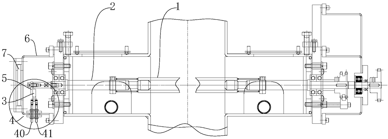
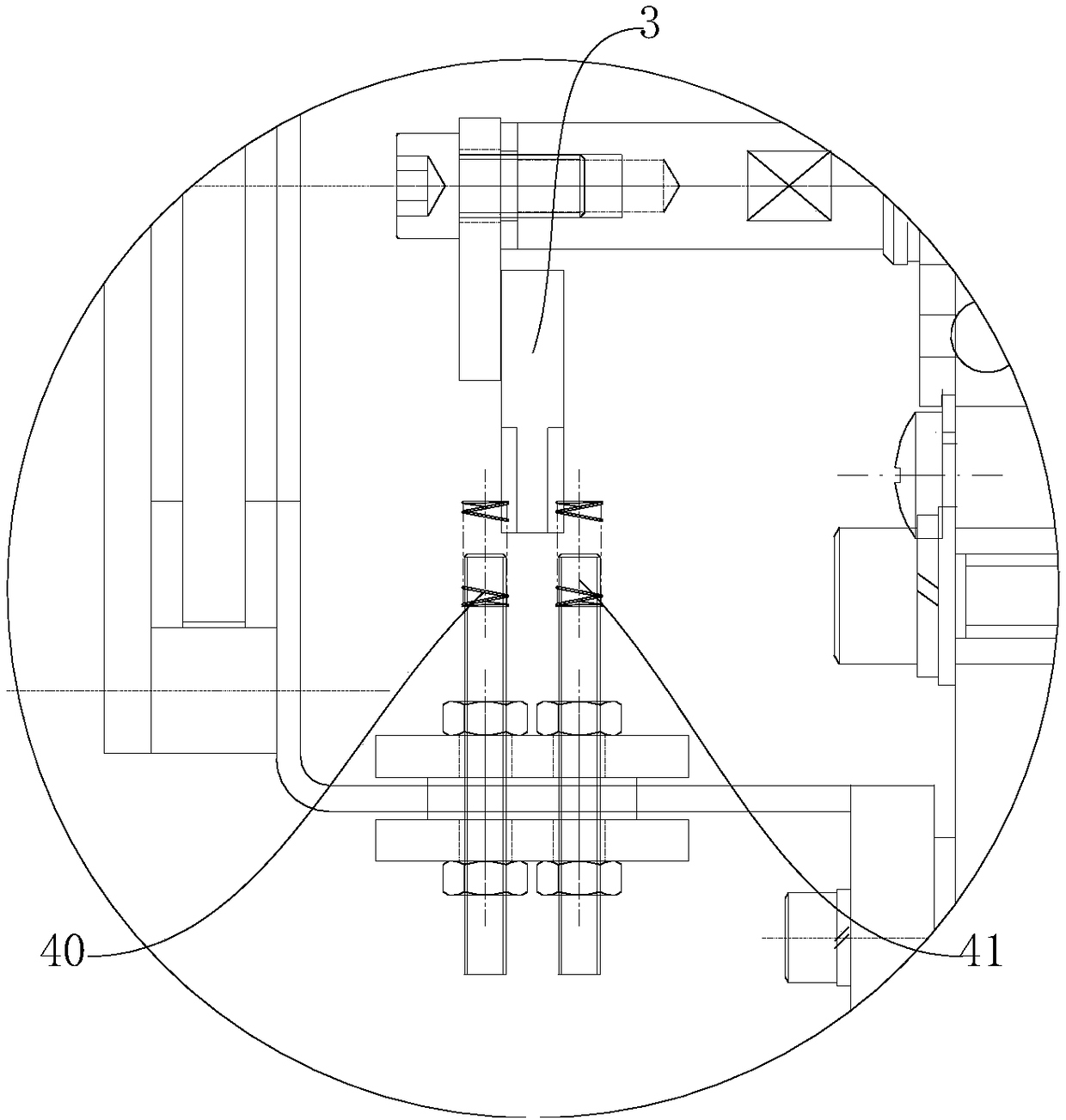
[0038] like figure 1 and figure 2 As shown, a broken rod detection device includes a transmission roller rod 1, which is characterized in that:
[0039] One end of the transmission roller 1 is connected and fixed with an outwardly extending rotating shaft 2, and the end of the rotating shaft 2 is fixedly connected with a trigger block 3 suitable for rotating therewith, and the outer side of the trigger block 3 is fixedly provided with a Corresponding signal generator 4;
[0040] When the transmission roller 1 rotates, it drives the rotating shaft 2 to rotate, and then drives the trigger block 3 to rotate accordingly. When the trigger block 3 rotates to contact with the signal generator 4, the signal generator 4 Generate a detection signal.
[0041] Wherein the signal generator 4 includes a positive electrode 40 and a negative electrode 41 arranged at intervals, and the trigger block 3 is a conductive element; when the trigger block 3 rotates with the rotating shaft 2, when the trigger block 3 rotates to The positive electrode 40 and the negative electrode 41 are in contact with the two respectively, and the positive and negative electrodes are connected to generate an electric signal.
[0042] Wherein the trigger block 3 is fixedly connected with the rotating shaft 2 by an insulating mounting block 5 .
[0043] Wherein the outer side of the detection device is also covered with a sealing cover 6 , and the outer side of the sealing cover 6 is also provided with an observation window 7 .
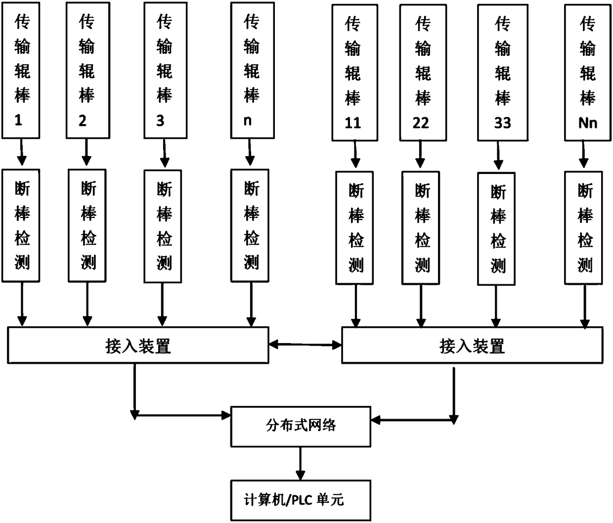
[0044] like image 3 Shown, a kind of broken rod automatic monitoring system, it comprises:
[0045] A plurality of transmission rollers and the above-mentioned broken rod detection device installed and connected to the end of the transmission roller in one-to-one correspondence, each of the transmission rollers and its corresponding broken rod detection device constitute a detection node, The detection node enters the distributed network through the access device;
[0046] When the transmission roller bar is broken during the process of transporting materials, the monitoring device enters the distributed network after obtaining the detection signal, and the detection node packs the alarm information through the network protocol and transmits it to the analysis center through the distributed network. The computer, the analysis computer judges and displays the position information of the broken rod through the network protocol analysis software, so as to monitor the running state of the transmission roller in real time.
[0047] Wherein, there is at least one access device, which respectively corresponds to a plurality of detection nodes.
[0048] Wherein the access device accesses the distributed network in a wired or wireless manner.
[0049] Wherein the number of distributed network nodes is greater than 1.
[0050] Wherein the number of network protocol layers of the distributed network is greater than two.
[0051] A roller kiln is a lithium battery material sintering roller kiln, and the roller kiln includes the above-mentioned automatic monitoring system for broken rods.
[0052]The design of the broken rod detection device of this technical solution adopts the contact type, which has the following advantages:
[0053] 1. For lithium battery sintering kilns, the magnetic induction switch is prone to failure when the temperature is too high. The contact type can effectively avoid this defect, and the atmosphere requirements are strict, so it is more applicable;
[0054] 2. The contact type can be used when the distance between the rollers is small, and the magnetic induction switch (non-contact type) is effective within a certain distance. If the distance between the two rollers is small, it is easy to cause misjudgment of the alarm.
[0055] In addition, the automatic monitoring system for broken rods in this technical solution has the following advantages:
[0056] 1. Save IO resources of traditional PLC;
[0057] 2. The monitoring network wiring is simple;
[0058] 3. Save the computer system resources of the upper computer;
[0059] 4. The location of the fault point is simple, fast and convenient.
[0060] In addition, the roller kiln in this technical solution has all the advantages of the above-mentioned broken rod detection device and broken rod automatic monitoring system, so it will not be repeated here.
[0061] Finally, it should be noted that: the above embodiments are only used to illustrate the technical solutions of the present invention, rather than limiting them; although the present invention has been described in detail with reference to the foregoing embodiments, those of ordinary skill in the art should understand that: It is still possible to modify the technical solutions described in the foregoing embodiments, or perform equivalent replacements for some or all of the technical features; and these modifications or replacements do not make the essence of the corresponding technical solutions deviate from the technical solutions of the various embodiments of the present invention. scope.

PUM

no PUM

Description & Claims & Application Information

We can also present the details of the Description, Claims and Application information to help users get a comprehensive understanding of the technical details of the patent, such as background art, summary of invention, brief description of drawings, description of embodiments, and other original content. On the other hand, users can also determine the specific scope of protection of the technology through the list of claims; as well as understand the changes in the life cycle of the technology with the presentation of the patent timeline. Login to view more.

Similar technology patents

Digital primary and secondary fusion ring main unit integrated system

InactiveCN113013993AEasy wiringlow cost
Owner:南京芯橙电力科技有限公司

Quick-connection terminal structure and BMS control panel

InactiveCN113690661AEasy wiring
Owner:安徽统凌科技新能源有限公司

Insulating bush

InactiveCN104682021AReduce the chance of short circuitsEasy wiring
Owner:STATE GRID CORP OF CHINA +1

Switching device of alternating current voltage stabilizer

ActiveCN113099645AEasy wiringConvenient wiring operation
Owner:KEHUA DATA CO LTD +1

Elevator calling and registering system and elevator

ActiveCN102745562ASave I/O resourcesVersatile
Owner:HITACHI ELEVATOR CHINA

Multichannel analog input detection circuit with trigger wake-up function

PendingCN111142449Alow power sleepSave I/O resources
Owner:SHENZHEN SOUTHERN DARE AUTOMOTIVE ELECTRONICS

Classification and recommendation of technical efficacy words

  • Save I/O resources

Elevator calling and registering system and elevator

ActiveCN102745562ASave I/O resourcesVersatile
Owner:HITACHI ELEVATOR CHINA

Multichannel analog input detection circuit with trigger wake-up function

PendingCN111142449Alow power sleepSave I/O resources
Owner:SHENZHEN SOUTHERN DARE AUTOMOTIVE ELECTRONICS
Why Eureka
Try Eureka