Dangerous material location fire monitoring method and system

A dangerous goods and cargo location technology, applied in the field of warehouse cargo location management, can solve the problems of easy dust interference, hysteresis, cumbersome monitoring point network design and other problems, achieve good economic and social benefits, and ensure accuracy Effect

Inactive Publication Date: 2018-09-14
BEIJING INSTITUTE OF PETROCHEMICAL TECHNOLOGY
View PDF5 Cites 5 Cited by
  • Summary
  • Abstract
  • Description
  • Claims
  • Application Information

AI Technical Summary

Problems solved by technology

[0004] The current point-type temperature-measuring detectors can only obtain information near the sampling point. To achieve overall supervision, cumbersome monitoring point network design is required. There

Method used


Image

  • Dangerous material location fire monitoring method and system
  • Dangerous material location fire monitoring method and system
  • Dangerous material location fire monitoring method and system

Examples


Embodiment 1

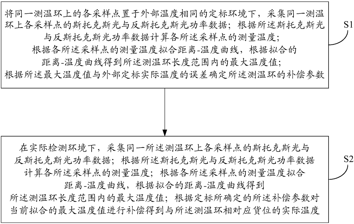
[0019] This embodiment discloses a fire monitoring method for a dangerous cargo space, such as figure 1 shown, including:

[0020] Step S1, place each sampling point on the same temperature measuring ring in a calibration environment with the same external temperature, and collect the Stokes light and anti-Stokes light power data of each sampling point on the same temperature measuring ring; The Stokes light and anti-Stokes light power data are used to calculate the measured temperature of each of the sampling points; the distance-temperature curve is fitted according to the measured temperature of each of the sampling points, and the distance-temperature curve is fitted according to the fitted distance-temperature curve Obtaining the maximum temperature value within the length range of the temperature measuring loop; determining the compensation parameters of the temperature measuring loop according to the error between the maximum temperature value and the actual temperature...

Embodiment 2

[0045] Corresponding to the above method embodiments, this embodiment discloses a fire monitoring system for dangerous cargo locations, including:

[0046] The first subsystem is used to place each sampling point on the same temperature measuring ring in a calibration environment with the same external temperature, and collect the Stokes light and anti-Stokes light of each sampling point on the same temperature measuring ring power data; calculate the measured temperature of each of the sampling points according to the Stokes light and anti-Stokes light power data; fit the distance-temperature curve according to the measured temperature of each of the sampling points, and The distance-temperature curve obtains the maximum temperature value within the length range of the temperature measuring ring; determines the compensation parameter of the temperature measuring ring according to the error between the maximum temperature value and the actual temperature of the external calibra...


PUM


Abstract

The invention relates to the warehouse location management technology field, discloses a dangerous material location fire monitoring method and system and aims to realize accurate monitoring of the dangerous material location fire based on fiber Raman scattering. The method comprises steps that each sampling point of the same temperature measuring ring is placed in the calibration environment withthe same external temperature to solve compensation parameters of the same temperature measuring ring; in the actual detection environment, Stokes light and anti-Stokes light power data of each sampling point on the same temperature measuring ring are collected; the measuring temperature of each of the sampling points is calculated based on the Stokes light and anti-Stokes light power data; a distance-temperature curve is fitted according to the measured temperature of each of the sampling points, and the maximum temperature value of the temperature measuring ring within the length range is acquired according to the fitted distance-temperature curve; according to the compensation parameters determined through calibration, the currently fitted maximum temperature value is compensated to acquire the actual temperature of the corresponding location of the temperature measuring ring.

Description

technical field [0001] The invention relates to the technical field of warehouse location management, in particular to a fire monitoring method and system for dangerous goods locations. Background technique [0002] With the continuous development of the economy, in order to maximize the utilization of space, more and more enterprises choose to use three-dimensional warehouses to store their goods. The three-dimensional warehouse is also called a high-rise shelf warehouse, an automatic storage system warehouse, etc. The warehouse adopts multi-layer shelves, and uses automatic material handling equipment to carry out goods in and out of the warehouse. The system structure presents a high degree of mechanization and automation. [0003] Due to the large amount of goods in the three-dimensional warehouse, the fire load per unit area of ​​the warehouse is generally high, and dangerous chemicals will cause even greater losses after an accident due to their physical characteristic...

Claims


Application Information

Patent Timeline
IPC IPC(8): G08B17/06G01K11/32
CPCG01K11/32G08B17/06G01K11/324
Inventor 刘学君卢浩袁碧贤李京戴波刘威威陈增强
Owner BEIJING INSTITUTE OF PETROCHEMICAL TECHNOLOGY
Why Eureka
Try Eureka