An LED chip mounter

A technology of LED placement machine and conveying mechanism, which is applied in the manufacture of electrical components, circuits, and printed circuits, etc., can solve the problems of low work efficiency and inability to meet large-scale production, and achieve compact structure, reduce production costs, and reduce damage rates. Effect

Active Publication Date: 2018-09-14
绍兴舜宇照明工程有限公司
View PDF6 Cites 5 Cited by
  • Summary
  • Abstract
  • Description
  • Claims
  • Application Information

AI Technical Summary

Problems solved by technology

The existing LED placement machine can only produce substrates of a single specification, and the work efficiency is relatively low, which cannot meet the needs of large-scale production.

Method used


Image

  • An LED chip mounter
  • An LED chip mounter
  • An LED chip mounter

Examples


Embodiment Construction

[0030] An LED placement machine of the present invention will be further described below in conjunction with the accompanying drawings.

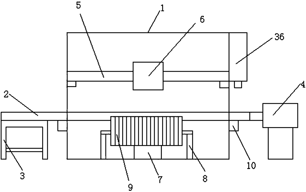
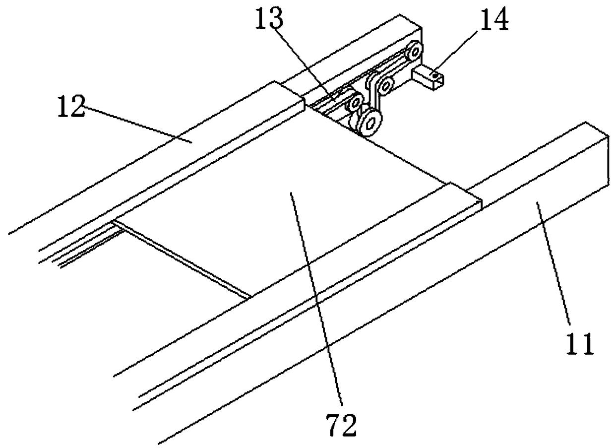
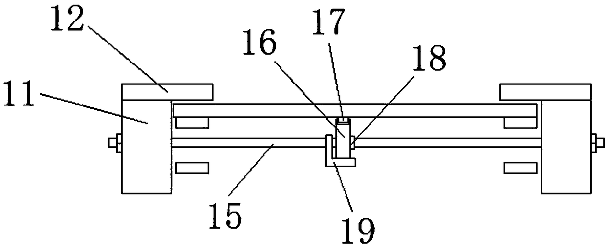
[0031] Such as Figure 1-10The LED placement machine shown includes a housing 1, a conveying mechanism 2, a width adjusting mechanism 10, a moving mechanism 5, a supporting mechanism 7, and a part picking and placing head 6. The conveying mechanism 2 is set in the middle of the housing 1, and the conveying mechanism 2 The left side of the lower part is provided with a feeding machine 3, the front side of the housing 1 is provided with a support frame 8, and a plurality of sheet taking supports 9 are provided on the support frame 8; the conveying mechanism 2 includes two side plates 11 arranged parallel to each other, The upper part is connected with a splint 12, and the inner side of the side plate 11 is provided with a conveyor belt 13. The conveyor belt 13 includes a conveyor belt and a number of driving wheels that drive the conveyor belt...


PUM


Abstract

The invention provides an LED chip mounter and belongs to the technical field of LED chip mounting processing. The LED chip mounter comprises a shell, a conveying mechanism, width adjusting mechanisms, a moving mechanism, a supporting mechanism and a part picking and placing head. The conveying mechanism is located at the middle position of the shell; a feeding machine base is arranged at the leftside of the lower portion of the conveying mechanism; a supporting rack is arranged at the front side of the shell and a plurality of chip fetching supports are arranged on the supporting rack; the conveying mechanism comprises two side plates which are arranged in parallel; the upper portions of the side plates are connected with clamping plates; the inner sides of the side plates are provided with conveying belts each of which comprises a conveying belt unit and a plurality of driving wheels driving the conveying belt unit to rotate. The LED chip mounter can finish chip mounting work stablywith high speed, can reduce production cost and has the advantages of compact structure, high speed and stability.

Description

technical field [0001] The invention discloses an LED patch machine, which belongs to the technical field of LED patch processing. Background technique [0002] At present, with the development of modern electronic components in the direction of miniaturization, integration and high reliability, especially in the face of increasingly fierce market competition, the production and manufacturing equipment of electronic products are moving towards high-speed, high-precision, intelligent , multi-function and other fully automated development. The assembly of electronic information products, especially the printed boards of key components, needs to be produced through the placement process. In recent years, with the development of the LED industry, new challenges have been brought to the overall performance of LED placement machines. The existing LED placement machines can only produce substrates of a single specification, and the work efficiency is relatively low, which cannot ...

Claims


Application Information

Patent Timeline
Patent Type & Authority Applications(China)
IPC IPC(8): H01L21/67H01L33/48H05K3/34
CPCH01L21/67253H01L33/48H01L2933/0033H05K3/341
Inventor 陈锦宏娄锦奇虞佳凯
Owner 绍兴舜宇照明工程有限公司
Why Eureka
Try Eureka