Lithium battery taping machine

A gluing machine, lithium battery technology, applied in the direction of non-aqueous electrolyte battery, electrolyte battery manufacturing, sustainable manufacturing/processing, etc.

Inactive Publication Date: 2018-09-14
留丹翠
View PDF0 Cites 17 Cited by
  • Summary
  • Abstract
  • Description
  • Claims
  • Application Information

AI Technical Summary

Problems solved by technology

[0003] The purpose of the present invention is to solve the existing problems of the existing lithium battery side-end glue, to provide a lithium battery sticker that can automatically adapt to the operation of different sizes of battery cells, and automatically complete the top surface glue and side-end glue operations. Melter

Method used


Image

  • Lithium battery taping machine
  • Lithium battery taping machine
  • Lithium battery taping machine

Examples


Embodiment Construction

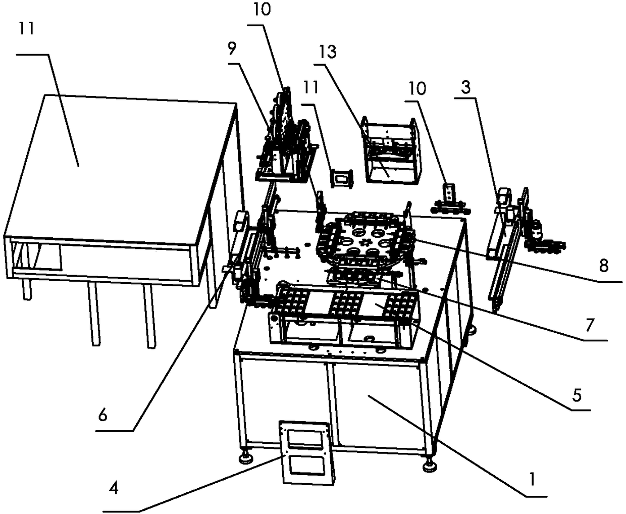
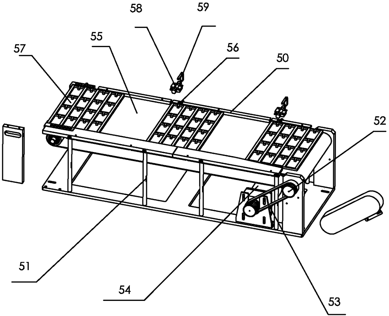
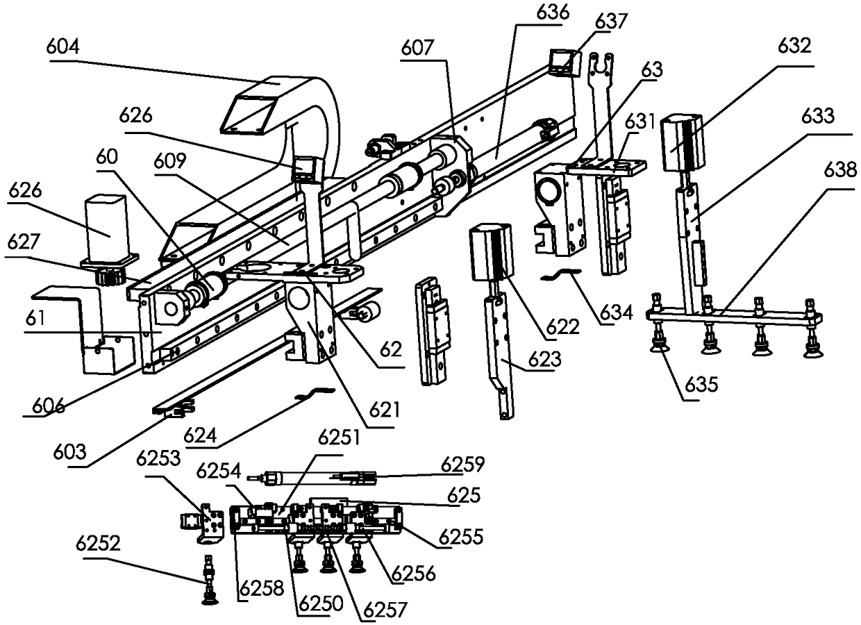
[0052] Combine below Figure 1-13 The present invention is further described.

[0053] Such as Figure 1-13 The lithium battery gluing machine shown includes a frame component 1, a control system, a support frame 4, a cell feeding component 5, a feeding manipulator component 6, a transfer component 7, a turntable component 8, a gluing component 9, and a gluing component 10. The rubberized assembly 13 and the unloading manipulator assembly 3. The support frame 4, the cell feeding assembly 5, the transfer assembly 7, the turntable assembly 8 and the glue application assembly 9 are fixed on the frame assembly 1, and the loading manipulator assembly 6, the glue pressing assembly 10 and the unloading manipulator assembly are installed on the support frame 4 superior. The control system controls the action of the cell feeding component 5, the loading manipulator component 6, the transfer component 7, the turntable component 8, the glue-applying component 9, the pressing component...


PUM


Abstract

The invention relates to the technical field of new energy production. A lithium battery taping machine comprises a frame component, a control system, a support frame, a cell feeding component, a feeding manipulator component, a transfer component, a turnplate component, a taping component, a tape pressing component, a tape covering component, and a discharging manipulator component. The lithium battery taping machine has the advantages that the machine may automatically adapt to taping of cells having different spaces, and top taping and lateral end tape covering are fully automated.

Description

technical field [0001] The invention relates to the technical field of new energy production, in particular to gluing equipment for lithium batteries. Background technique [0002] Lithium battery surface gluing is an important process in the production process of lithium batteries. Lithium battery gluing includes top surface gluing, double-sided gluing, top surface gluing and end bread gluing, etc. Top surface gluing and double-sided gluing are relatively Convenience. At present, automatic operations are used, but it is difficult to automate the top surface and side-end breading. Because the accuracy of the side-end breading is difficult to control, most of the processes involving side-end breading are still manual operations. In addition, in the existing automatic lithium battery gluing equipment, the feeding manipulator or the unloading manipulator generally uses the suction cup assembly to absorb the battery cell. In order to improve work efficiency, the feeding manipula...

Claims


Application Information

Patent Timeline
Patent Type & Authority Applications(China)
IPC IPC(8): H01M10/058
CPCH01M10/058Y02E60/10Y02P70/50
Inventor 留丹翠
Owner 留丹翠
Why Eureka
Try Eureka