A tracking adjustment device for photovoltaic panels

A photovoltaic cell panel and adjusting device technology, applied in photovoltaic power generation, photovoltaic module support structure, photovoltaic modules and other directions, can solve the problems of easy rust, increased load of the adjusting device, etc., to achieve flexible operation, reduce angular momentum, and long-term use effect of life

Active Publication Date: 2020-07-17
中电投新疆能源化工集团哈密有限公司
View PDF11 Cites 0 Cited by
  • Summary
  • Abstract
  • Description
  • Claims
  • Application Information

AI Technical Summary

Problems solved by technology

[0005] Chinese patent CN201621024648.3 discloses a tracking adjustment device for photovoltaic panels, including a base; a rotating support whose axis is perpendicular to the base, the lower end is mounted on the base in a manner that can rotate around its axis, and the upper end is hinged to the photovoltaic panel; Steering adjustment mechanism, which includes an azimuth adjustment unit that drives the rotation of the rotating pillar and an elevation adjustment unit for adjusting the elevation angle of the photovoltaic cell panel; a light sensor, which is arranged on the photovoltaic cell panel to sense the direction of sunlight irradiation; and a controller , which are respectively connected with the light sensor and the steering adjustment mechanism, and are used to control the steering adjustment mechanism to adjust the azimuth and elevation angles of the photovoltaic panel. The device on the rotating support increases the load on the entire adjustment device. In addition, the rolling bearing of the tracking adjustment device of the photovoltaic panel is exposed outside, which is easy to rust in a humid environment.

Method used


Image

  • A tracking adjustment device for photovoltaic panels
  • A tracking adjustment device for photovoltaic panels
  • A tracking adjustment device for photovoltaic panels

Examples


Embodiment Construction

[0030] The following will clearly and completely describe the technical solutions in the embodiments of the present invention with reference to the accompanying drawings in the embodiments of the present invention. Obviously, the described embodiments are only some, not all, embodiments of the present invention. Based on the embodiments of the present invention, all other embodiments obtained by persons of ordinary skill in the art without making creative efforts belong to the protection scope of the present invention.

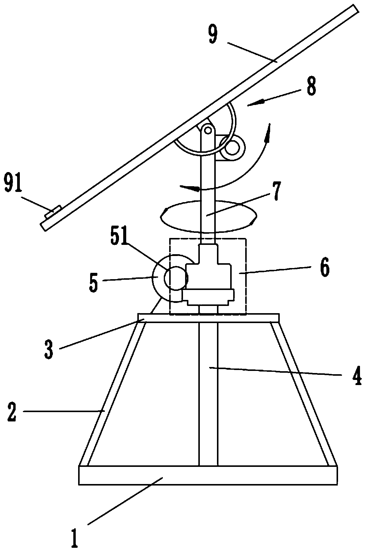
[0031] refer to Figure 1 to Figure 7 ,Such as figure 1 The tracking adjustment device for photovoltaic panels shown includes a base 1, several support rods 2, a central support shaft 4, a second drive system 8 and a battery panel 9, the base 1 is horizontally fixed on the ground, and the support rods 2 are inclined fixed on the base 1, the upper end of the support rod 2 is horizontally fixed with a support plate 3, the first drive system 5 is arranged on the...


PUM


Abstract

The invention discloses a tracking and regulating device for a photovoltaic cell panel. The tracking and regulating device comprises a base, a plurality of support rods, a center support shaft, a second drive system and the cell panel, the base is horizontally fixed on the ground, the support rods are slantly fixed on the base, a support plate is fixed horizontally at the upper end of the supportrod, a first drive system is arranged on the support plate, the lower end of the center support shaft is fixed on the base, the upper end of the center support shaft penetrates through the support plate, the upper end of the center support shaft is coaxially connected with a rotating shaft, the cell panel is hinged at the top end of the rotating shaft, the second drive system is arranged on the upper section of the rotating shaft and is connected with the cell panel, the second drive system drives the cell panel to do rotary swinging motion around the hinging center, the tracking and regulating device further comprises a connecting structure, and the center support shaft is connected with the rotating shaft through the connecting structure. Due to the adoption of the structure, the tracking and regulating device operates flexibly and lightly and has certain anti-corrosion capability, and the photovoltaic cell panel has a longer service life.

Description

technical field [0001] The invention relates to the technical field of photovoltaic power generation, in particular to a tracking adjustment device for photovoltaic battery panels. Background technique [0002] Solar energy is a kind of renewable energy. It is extensive, safe, huge and long-lasting, and it is not controlled or monopolized by anyone. It is given to human beings selflessly, free and equitably. Under the background of increasing pressure, many countries in the world have set off a trend of developing and utilizing solar energy. The application field of solar energy has continued to expand and has penetrated into every corner of our lives. [0003] Photovoltaic cells are used to directly convert the sun's light energy into electrical energy. Photovoltaic cells, as a relatively mature application of solar energy at this stage, have been widely used in our lives. On our roofs, ridges, often Solar panels can be seen. [0004] The sun rises in the east and sets in...

Claims


Application Information

Patent Timeline
Patent Type & Authority Patents(China)
IPC IPC(8): H02S20/32F24S30/422
CPCH02S20/32Y02E10/50
Inventor 林芳芳
Owner 中电投新疆能源化工集团哈密有限公司
Why Eureka
Try Eureka