Refrigerator

A technology for a refrigerator and a storage room, which is applied in the field of refrigerators, can solve the problems of the compressor 50 not functioning, the discharge piping is brittle, and the compression cannot be performed, and achieves the effects of reducing the radius of the switch track, suppressing abnormal collisions, and reducing angular momentum.

Active Publication Date: 2007-11-07
PANASONIC CORP
View PDF2 Cites 0 Cited by
  • Summary
  • Abstract
  • Description
  • Claims
  • Application Information

AI Technical Summary

Problems solved by technology

[0014] In addition, if the airtight container 52 is in contact with the cylinder group 59 constituting the compression member 63, etc., since both are formed of metal, metal chips (fine fragments) will be generated.
If it gets between the cylinder block 59 and the crankshaft 68 which is a typical shaft slip, there is a possibility of abnormal wear and loss of compression (lockup)
[0015] On the other hand, in the compressor 50, there is attached a refrigerant piping (not shown) that conveys the compressed refrigerant 53 to the next step, such as a discharge capillary. If the parts constituting the compression member 63 are in frequent contact, metal fatigue will concentrate and accumulate in the contact parts, and eventually the discharge pipe will be brittle and the compressor 50 will not be able to perform the prescribed function.

Method used


Image

  • Refrigerator
  • Refrigerator
  • Refrigerator

Examples


Embodiment approach 1

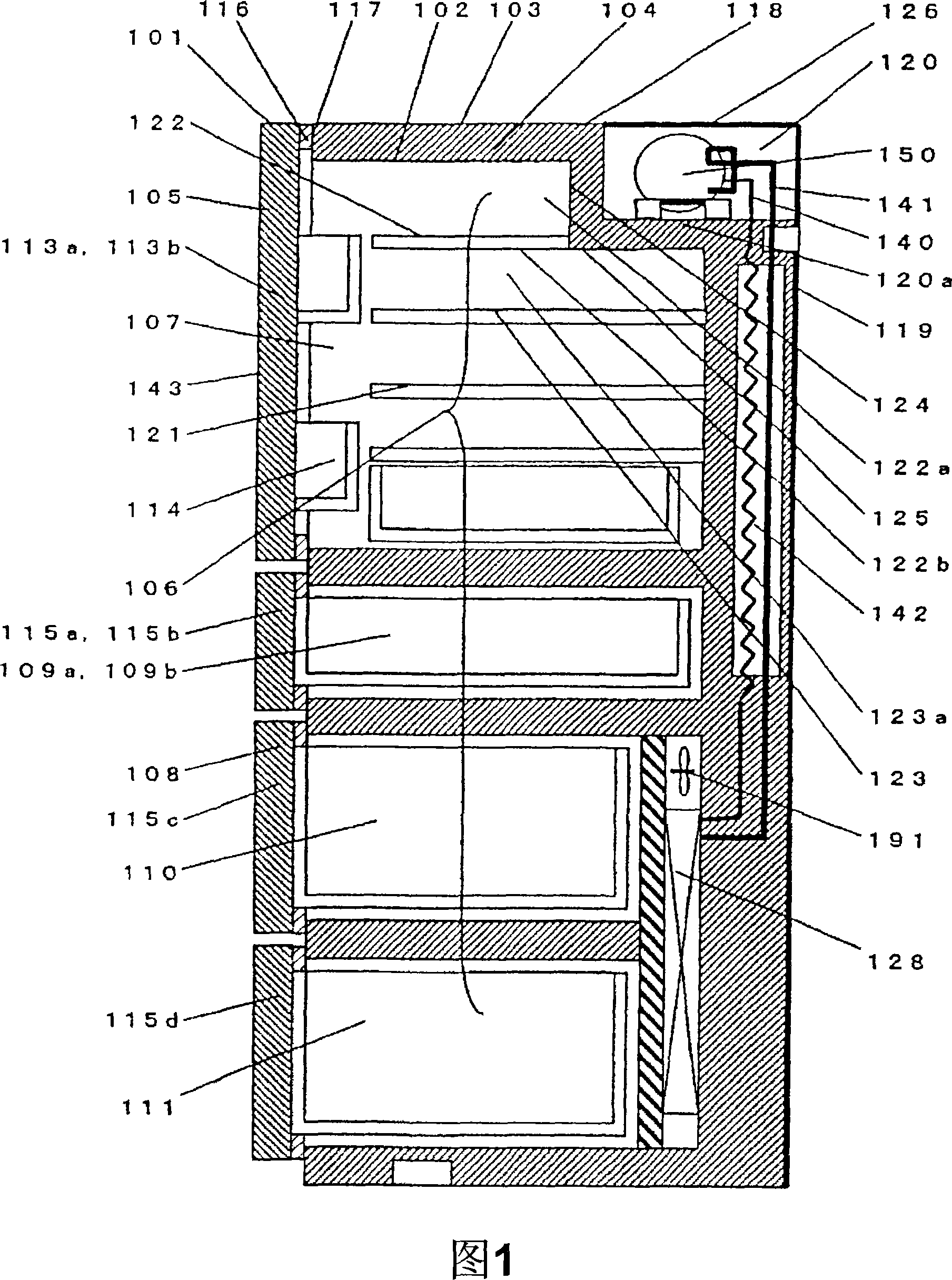
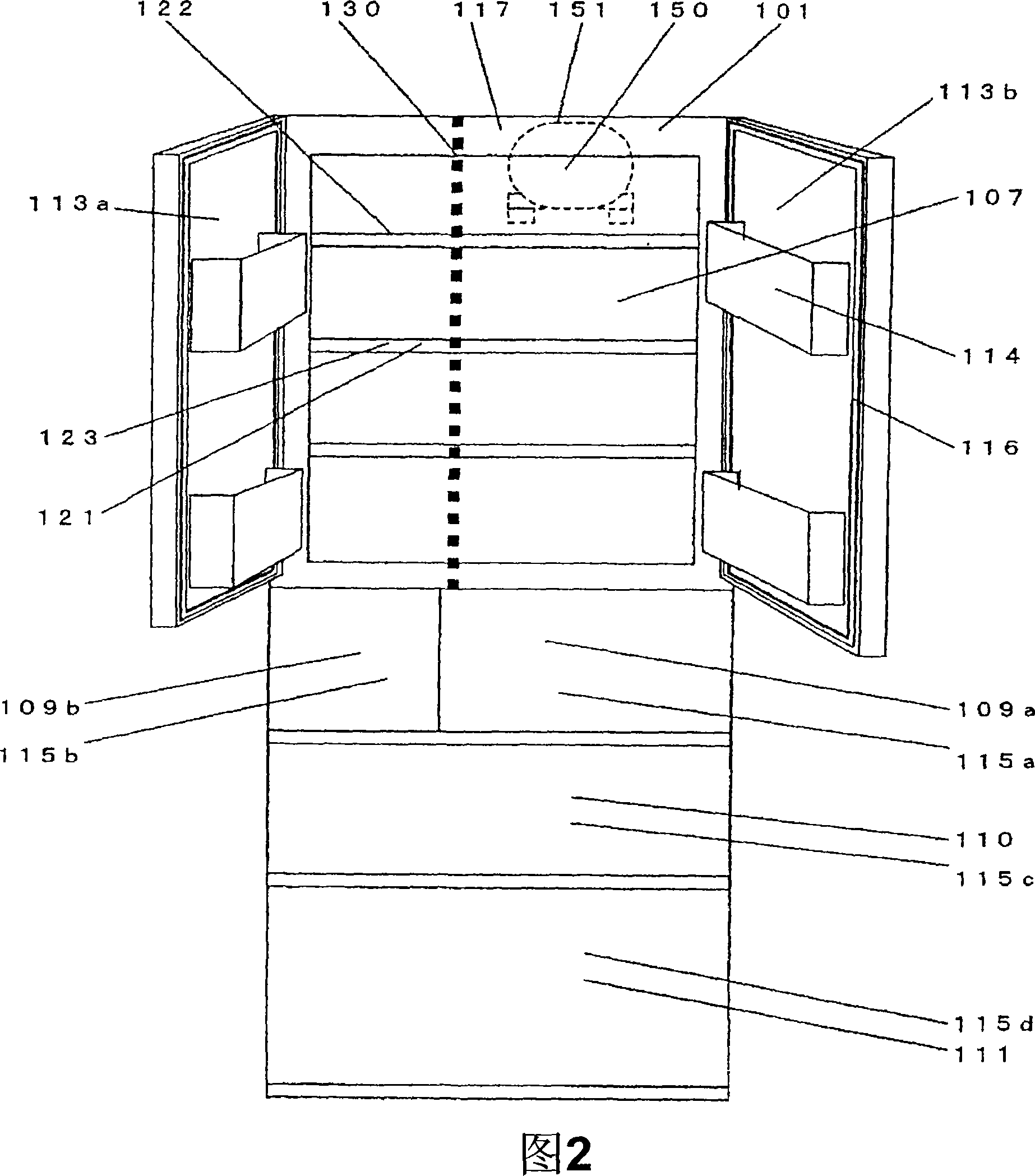
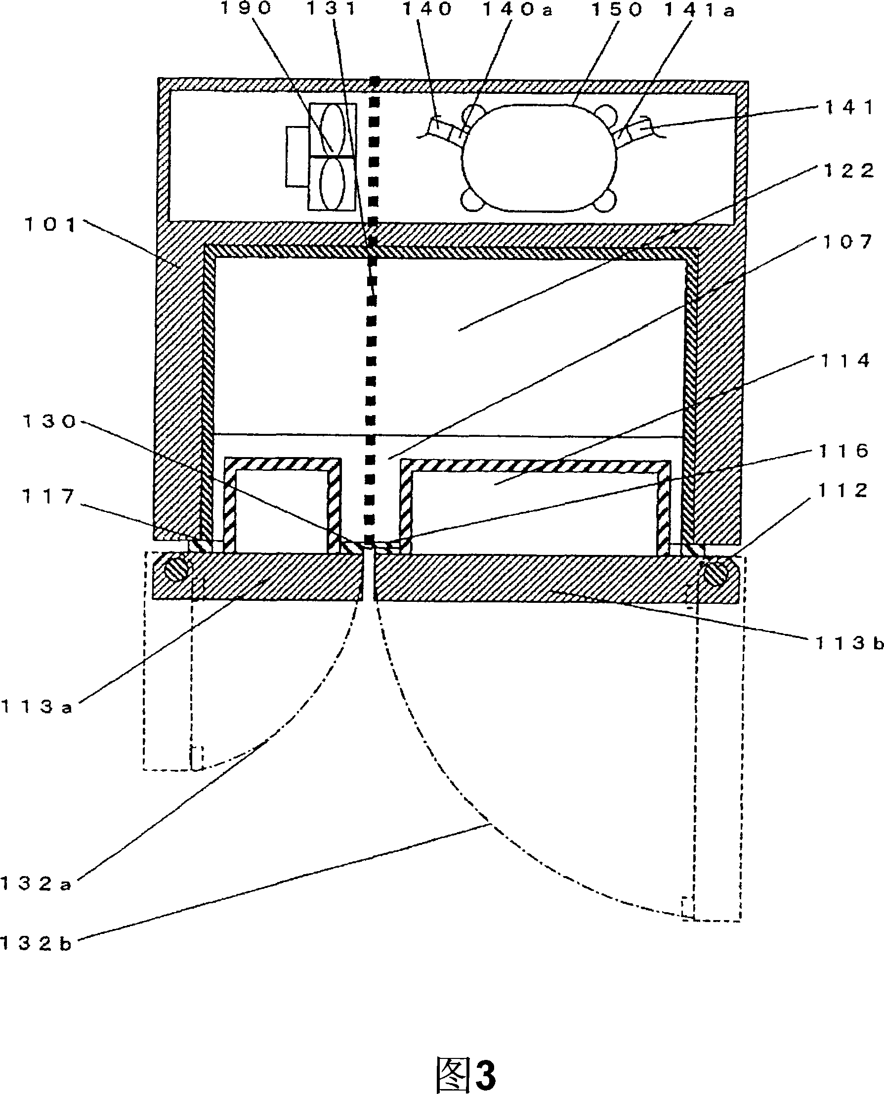
[0124] Fig. 1 is a structural sectional view of a refrigerator according to Embodiment 1 of the present invention, Fig. 2 is a front view of the refrigerator according to the same embodiment, and Fig. 3 is a view from above of the refrigerator according to the same embodiment. Figure 4 is a longitudinal sectional view of the compressor seen from the back of the refrigerator according to the same embodiment, and Figure 5 is a view from the top of the refrigerator in the same embodiment 6 is a schematic diagram for explaining the operation of the compressor when the revolving door related to the same embodiment is closed.

[0125] Next, Embodiment 1 of the present invention will be described with reference to FIGS. 1 to 6 .

[0126] In Fig. 1 to Fig. 6, the refrigerator has a compressor 150 connected in a ring shape, a discharge pipe 140 connected to the compressor 150, a condenser (not shown), and a pressure reducer built in the box body 101. A refrigerating cycle constituted ...

Embodiment approach 2

[0174] 7 is a structural sectional view of a refrigerator according to Embodiment 2 of the present invention, FIG. 8 is a front view of the refrigerator according to the same embodiment, and FIG. 9 is a view from above of the refrigerator according to the same embodiment. 10 is a schematic cross-sectional view of the opening and closing trajectory of the revolving door seen from the lateral direction of the refrigerator according to the same embodiment.

[0175] Next, Embodiment 2 will be described based on FIGS. 7 , 8 , 9 and 10 . The same structures as those in Embodiment 1 are given the same reference numerals, and detailed descriptions thereof are omitted.

[0176] In FIGS. 7 to 10 , the refrigerator includes a compressor 150 , a discharge pipe 140 connected to the compressor 150 , and a condenser (not shown). Inside the box body 201 are built-in a capillary tube 142 connected in a ring as a pressure reducer, a drier (not shown) for removing moisture, an evaporator (128) ...

Embodiment approach 3

[0189] Fig. 11 is a structural sectional view of the refrigerator according to Embodiment 3 of the present invention, Fig. 12 is a front view of the refrigerator according to the same embodiment, and Fig. 13 is a view from above of the refrigerator according to the same embodiment. Fig. 14 is a schematic sectional view of the opening and closing trajectory of the revolving door seen from the lateral direction of the refrigerator according to the same embodiment.

[0190]Next, Embodiment 3 will be described based on FIG. 11 , FIG. 12 , FIG. 13 and FIG. 14 . The same symbols are assigned to the same structures as in Embodiment 1. FIG.

[0191] In FIGS. 11 to 14 , the refrigerator includes a compressor 150 , a discharge pipe 140 connected to the compressor 150 , a condenser (not shown), and a capillary 142 as a pressure reducer. In addition, a refrigerating cycle in which a drier (not shown) for removing moisture, an evaporator 128 with an internal fan 191 arranged nearby, and a...


PUM


Abstract

A highly reliable refrigerator which is rendered silent by suppressing abnormal noise from a compressor due to impact of collision against the box body of refrigerator when a rotary door is closed. The refrigerator comprises a box body (101) arranged with a storage compartment (106) provided with opening/closing rotary doors (113a, 113b) on the front. A recess (120) curved toward the uppermost containing space (122a) side in the storage compartment (106) is provided across the top and back of the box body (101). The compressor (150) is installed in the recess (120). The rotary doors (113a, 113b) are split to open at the middle with the right and left sides as fulcrums, and the compressor (150) is arranged so as to avoid the projection line from the front side of the split line. Abnormal noise from the compressor (150) is suppressed by separating it from the projection line from the front side of the split line where angular momentum is highest thereby reducing impact being transmitted to the compressor (150) through the refrigerator box body when the rotary doors (113a, 113b) are closed.

Description

technical field [0001] The present invention relates to a refrigerator in which a compressor is mounted in a concave portion on a top surface of the refrigerator. Background technique [0002] Recently, from the viewpoint of protecting the global environment, the energy-saving trend of refrigerators has become stronger and stronger. In addition to improving its usability and storage, it is also required to further reduce its noise from the viewpoint of improving comfort. . [0003] In the prior art, such a refrigerator has always adopted a method in which a compressor or the like forming a machine room is arranged on the top surface of the refrigerator body or the upper back of the refrigerator body which is poor in usability from the user's side (for example, Japanese Patent Laid-Open , Special Publication No. 11-183014). [0004] Hereinafter, the above-mentioned conventional refrigerator will be described with reference to the drawings. Fig. 22 is a structural sectional...

Claims


Application Information

Patent Timeline
Patent Type & Authority Applications(China)
IPC IPC(8): F25D19/00
Inventor 石田贵规
Owner PANASONIC CORP
Why Eureka
Try Eureka