Adaptive OLT optical module and control method thereof
An optical module and self-adaptive technology, applied in the field of optical communication, can solve problems such as waste of resources and costs, inconvenient maintenance for operators, poor versatility, etc., and achieve the effect of reducing operation and maintenance costs and improving networking flexibility
- Summary
- Abstract
- Description
- Claims
- Application Information
AI Technical Summary
Problems solved by technology
Method used
Image
Examples
Embodiment 1
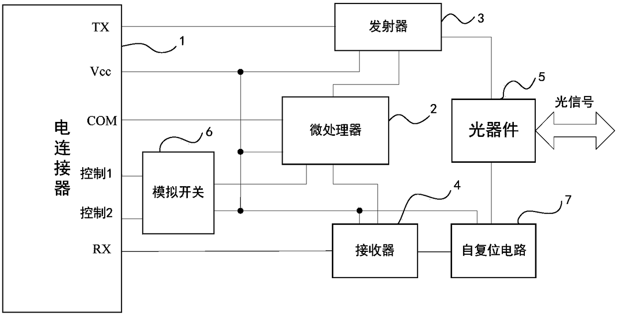
[0051] Embodiment 1 of the present invention provides an adaptive OLT optical module, such as image 3 and Figure 7 As shown, it includes an electrical connector, a microprocessor, a transmitter, a receiver and an optical device, wherein the microprocessor is respectively connected to the transmitter and the receiver, and the optical module also includes an analog switch and a self-resetting circuit, specifically;
[0052] The control port of the electrical connector is connected to the microprocessor for transmitting peripheral control signals to the microprocessor, wherein the control signal is used for the microprocessor to issue instructions to control the transmitter, Operating parameters of receivers and / or analog switches;
[0053] The control 1 signal port and the control 2 signal port of the electrical connector are connected to the strobe interface of the analog switch, and the strobe control interface of the analog switch receives a signal from the microprocessor,...
Embodiment 2
[0065] After providing the adaptive OLT optical module described in Embodiment 1, the embodiment of the present invention also provides a control method of the adaptive OLT optical module, and the control method may be based on but not limited to that provided in Embodiment 1 The adaptive OLT optical module completes the application. When the OLT optical module is inserted into the GPON system equipment, the microprocessor receives instructions from the system, and the microprocessor controls the analog switch so that the 9-pin Trigger signal of the electrical connector is connected to the microprocessor's Trigger input terminal, refer to as Figure 7 and Figure 8 As shown in the structural schematic diagram, the control method includes:
[0066] The optical device converts the uplink optical signal into an uplink electrical signal, and the uplink electrical signal is coupled to the receiver through capacitor C1 and capacitor C2; among them, capacitor C1, capacitor C2, resis...
PUM
 Abstract
Description
Claims
Application Information
 - R&D
- Intellectual Property
- Life Sciences
- Materials
- Tech Scout
- Unparalleled Data Quality
- Higher Quality Content
- 60% Fewer Hallucinations
Browse by: Latest US Patents, China's latest patents, Technical Efficacy Thesaurus, Application Domain, Technology Topic, Popular Technical Reports.
© 2025 PatSnap. All rights reserved.Legal|Privacy policy|Modern Slavery Act Transparency Statement|Sitemap|About US| Contact US: help@patsnap.com


