
Steel ball immersion oil storage bucket and application method

A technology of steel balls and dresses, which is applied to the device and coating of the surface coating liquid, can solve the problems of easy corrosion, etc., and achieve the effects of prolonging the service life, reducing rust, and good oil resistance

Pending Publication Date: 2018-09-18
MAANSHAN YIFENG INDAL GROUP
View PDF2 Cites 2 Cited by
  • Summary
  • Abstract
  • Description
  • Claims
  • Application Information

AI Technical Summary

Problems solved by technology

[0006] Aiming at the problem that the surface of the existing steel balls is prone to rust during storage and transportation, the invention provides a steel ball oil-immersed container and its use method. The produced steel balls are treated with oil so that the surface of the steel balls is wrapped Oil layer can effectively reduce the corrosion of steel balls and meet customers' requirements for steel ball quality

Method used


Image

  • Steel ball immersion oil storage bucket and application method
  • Steel ball immersion oil storage bucket and application method
  • Steel ball immersion oil storage bucket and application method

Examples


Embodiment 1

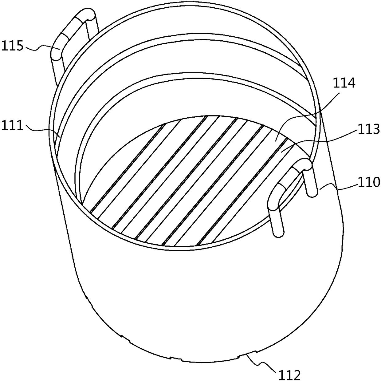
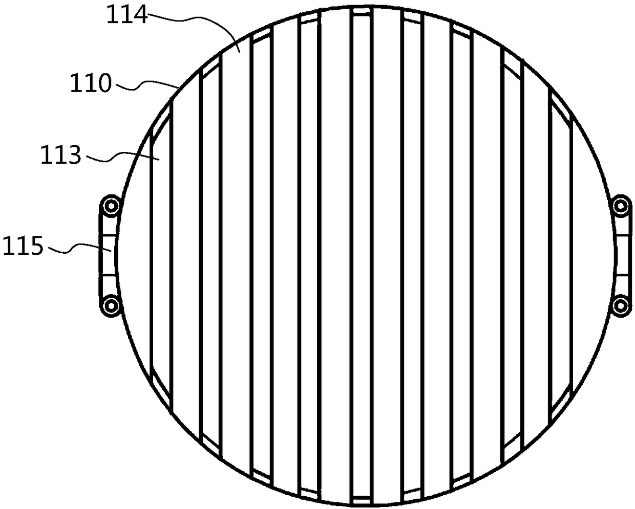
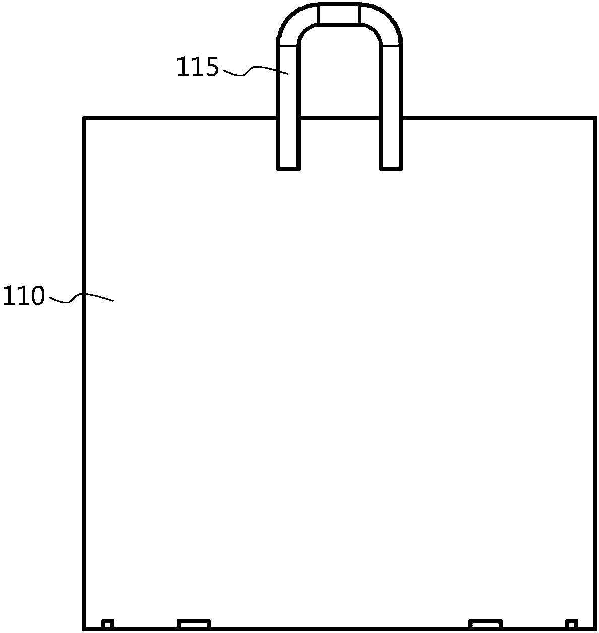
[0038] see Figure 1 to Figure 5 , describing a steel ball immersion oil container according to a preferred embodiment of the present invention, wherein, figure 1 It is a structural schematic diagram of the steel ball immersion oil containing barrel of the present invention; figure 2 It is the bottom view of the steel ball immersion oil containing barrel of the present invention; image 3 It is the front view of the steel ball immersion oil containing barrel of the present invention; Figure 4 It is the top view of the steel ball immersion oil containing barrel of the present invention; Figure 5 It is another structural schematic diagram of the steel ball immersion oil storage barrel of the present invention.

[0039] Such as Figure 1 to Figure 5As shown, a steel ball oil-immersed barrel in this embodiment includes a barrel body 110 whose cross-section is circular or oval, and at least one spiral groove 111 is opened on the inner wall of the barrel body 110, and the spi...

Embodiment 2

[0048] The basic structure of the present embodiment is consistent with that of Embodiment 1, except that the bucket also includes a goal funnel 120, the goal funnel 120 is conical, wherein the cone head is downward, and the lower end surface of the cone head is in contact with the partition. The distance between the bars 113 is greater than the diameter of the steel balls to be loaded, and the goal funnel 120 overlaps with the top edge of the barrel body 110 . If the steel balls are directly poured into the barrel, the spacer will be damaged or bent due to the large impact force of the steel balls, which will affect the service life of the barrel.

[0049] A method for using a steel ball immersion oil containing barrel of the present invention comprises the following steps:

[0050] S101, lap the goal funnel 120 on the barrel body 110 with the cone head facing down, and fix the goal funnel 120;

[0051] S102. Then pour the steel balls into the goal funnel 120, and the steel ...


PUM

PropertyMeasurementUnit
Thicknessaaaaaaaaaa
Granularityaaaaaaaaaa

Abstract

The invention discloses a steel ball immersion oil storage bucket and an application method and belongs to the technical field of production of steel balls. The steel ball immersion oil storage bucketcomprises a bucket body; the section of the bucket body is circular or elliptic; the inner sidewall of the bucket body is provided with at least one spiral groove; the bottom of the bucket body is opened and is provided with a mounting groove; the mounting groove is provided with a plurality of isolating bars; a plurality of oil charging clearances are formed among the isolating bars; the surfacetension of oil is increased due to the spiral groove and is larger than the adhesive force, so rising of the oil is quickened; a produced steel ball is subjected to oil immersion treatment so that the surface of the steel ball is coated with an oil layer, and thus corrosion of the steel ball is effectively reduced and the steel ball meets the quality requirements of customers.

Description

technical field [0001] The invention belongs to the technical field of steel ball production, and more specifically relates to a steel ball oil-immersed bucket and a use method thereof. Background technique [0002] Steel ball is a general term for steel balls, steel segments and special-shaped grinding bodies. From the shape, it can be divided into perfect round ball, capsule ball, ellipse ball, yin and yang ball, hollow ball, multi-faceted ball, multi-missing ball, etc. The production methods of steel balls generally include forging, rolling, semi-solid forming and casting. category. Steel balls are important basic components, especially precision industrial steel balls play a huge role in the development of the national economy. Under some special conditions, steel balls of special materials are often required to complete the functions to be achieved in different environments. Steel balls, as the basic components in our daily life mechanical parts, play a huge role. Us...

Claims


Application Information

Patent Timeline
IPC IPC(8): B05C3/10
CPCB05C3/10
Inventor 潘政桃张学伍
Owner MAANSHAN YIFENG INDAL GROUP
Learn More